
Battery discharging control circuit

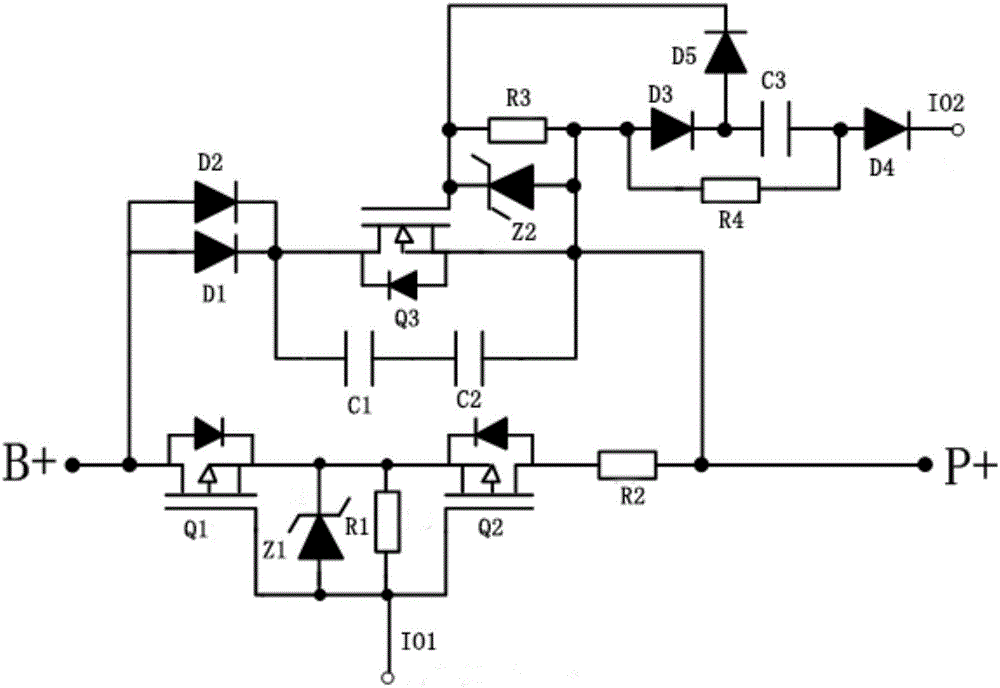
A discharge control and battery pack technology, applied in battery circuit devices, circuit devices, load supply circuits, etc., can solve the problems of reduced reliability and safety, complicated power-off and power-off strategies, and prone to sticking.

Inactive Publication Date: 2017-12-29
HUIZHOU BNET TECH CO LTD
View PDF0 Cites 4 Cited by
  • Summary
  • Abstract
  • Description
  • Claims
  • Application Information

AI Technical Summary

Problems solved by technology

Although this method can solve the problem of peak current at the moment of discharge to a certain extent, with the continuous complexity of the circuit, the blindly increasing the number of relays makes the power-on and power-off strategy extremely complicated
In addition, the relay has a problem that is difficult to solve: it is prone to sticking when working, and an anti-sticking mechanism needs to be added
This means adding an additional anti-sticking control circuit, making the battery management system more complex, and reducing reliability and safety

Method used


Image

  • Battery discharging control circuit
  • Battery discharging control circuit

Examples


Embodiment Construction

[0029] In order to facilitate understanding of the present invention, the present invention will be described more fully hereinafter with reference to the related drawings. The preferred embodiments of the invention are shown in the accompanying drawings. However, the present invention may be embodied in many different forms and is not limited to the embodiments described herein. Rather, these embodiments are provided so that a thorough and complete understanding of the present disclosure is provided.

[0030] It should be noted that when an element is referred to as being "fixed to" another element, it can be directly on the other element or intervening elements may also be present. When an element is referred to as being "connected" to another element, it can be directly connected to the other element or intervening elements may also be present. The terms "vertical", "horizontal", "left", "right" and similar expressions used herein are for the purpose of illustration only ...


PUM


Abstract

A discharge control circuit for a battery pack, comprising: a pre-discharge unit, a discharge unit, a start unit and a control unit, the input end of the pre-discharge unit is connected to the total positive end of the battery pack, the output end is connected to an external load, the input control end is connected to the control The first output control terminal of the unit is connected; the input terminal of the discharge unit is connected to the total positive terminal of the battery pack, the input control terminal is connected to the output control terminal of the starting unit, and the output terminal is connected to an external load; the first input control terminal of the starting unit It is connected with the output terminal of the discharge unit, and the second input control terminal is connected with the second output control terminal of the control unit. The control unit of the present invention controls the power MOS tube to disconnect and start the pre-discharge unit and the discharge unit, starts the pre-discharge unit to work at the moment of discharge, uses the power resistance of the pre-discharge unit to absorb the peak current, and then disconnects the pre-discharge unit to start the discharge unit , to realize the safe discharge of the battery pack to the external load.

Description

technical field [0001] The invention relates to the field of battery pack discharge, in particular to a battery pack discharge control circuit. Background technique [0002] When the battery pack starts to discharge, the discharge current jumps from zero instantaneously to several times or even several times the rated discharge current, and the current change rate is quite large, and this current is the peak pulse current. The impact damage to the key components of the main circuit of the battery management system and the battery pack is very large due to the peak pulse current. Frequent startup for a long time will greatly reduce the cycle life of the battery management system and key components. [0003] In many existing battery management systems, in order to reduce or absorb the discharge current, a pre-discharge unit and its control circuit are added to the circuit. The usual practice is: use the positive relay to realize the closing and opening of the total positive e...

Claims


Application Information

Patent Timeline
IPC IPC(8): H02J7/00
CPCH02J7/0063H02J7/0029
Inventor 贺亮
Owner HUIZHOU BNET TECH CO LTD
Learn More