Inverse time protection optimization method and system

A technology of inverse time protection and optimization method, which is applied in the direction of emergency protection circuit device, automatic disconnection emergency protection device, parameter calibration/setting, etc., and can solve the problems of slow action speed, complex structure of backup protection system and high equipment investment problem, to achieve performance improvement, good practical application value, and obvious performance

Inactive Publication Date: 2017-12-29
HUAZHONG UNIV OF SCI & TECH +1
View PDF7 Cites 5 Cited by
  • Summary
  • Abstract
  • Description
  • Claims
  • Application Information

AI Technical Summary

Problems solved by technology

Judging from the current situation, the protection configuration of the current smart substation does not take advantage of some technical advantages of the smart substation to optimize the backup protection, and there are still inherent defects in the traditional backup protection; the selectivity is guaranteed through the cooperation of fixed value and time, The action speed is slow; each component is equipped with multiple backup protection protection system complex structure and high investment in equipment

Method used


Image

  • Inverse time protection optimization method and system
  • Inverse time protection optimization method and system
  • Inverse time protection optimization method and system

Examples


Embodiment 1

[0055] An optimization method 100 for inverse time-limit protection, such as figure 1 shown, including:

[0056] Step 110, according to the station domain information, the inverse time-lag protection curve equation and the preset selectivity time difference, determine whether the inverse time-lag protection has selectivity in the power grid topology system where the line fault location is located.

[0057] Step 120, when the inverse time protection is not selective, calculate the corrected voltage on the high voltage side of the transformer in the grid topology system according to the station domain information.

[0058] Step 130 , correcting the inverse time-lag characteristic curve equation by using the corrected voltage at the high voltage side of the transformer and the compensation percentage to obtain a first corrected inverse time-lag characteristic curve equation.

[0059] Step 140: Adjust the compensation percentage according to the first modified inverse time lag ch...

Embodiment 2

[0064] On the basis of Embodiment 1, the station domain information includes: the line current passing through each protection device in the grid topology system when a line fault occurs at the line fault location, the protection starting current of each protection device after a line fault occurs, and the protection current of each protection device when a line fault occurs. The measured voltage across the device and the operating voltage of the grid topology system before the line fault occurs.

Embodiment 3

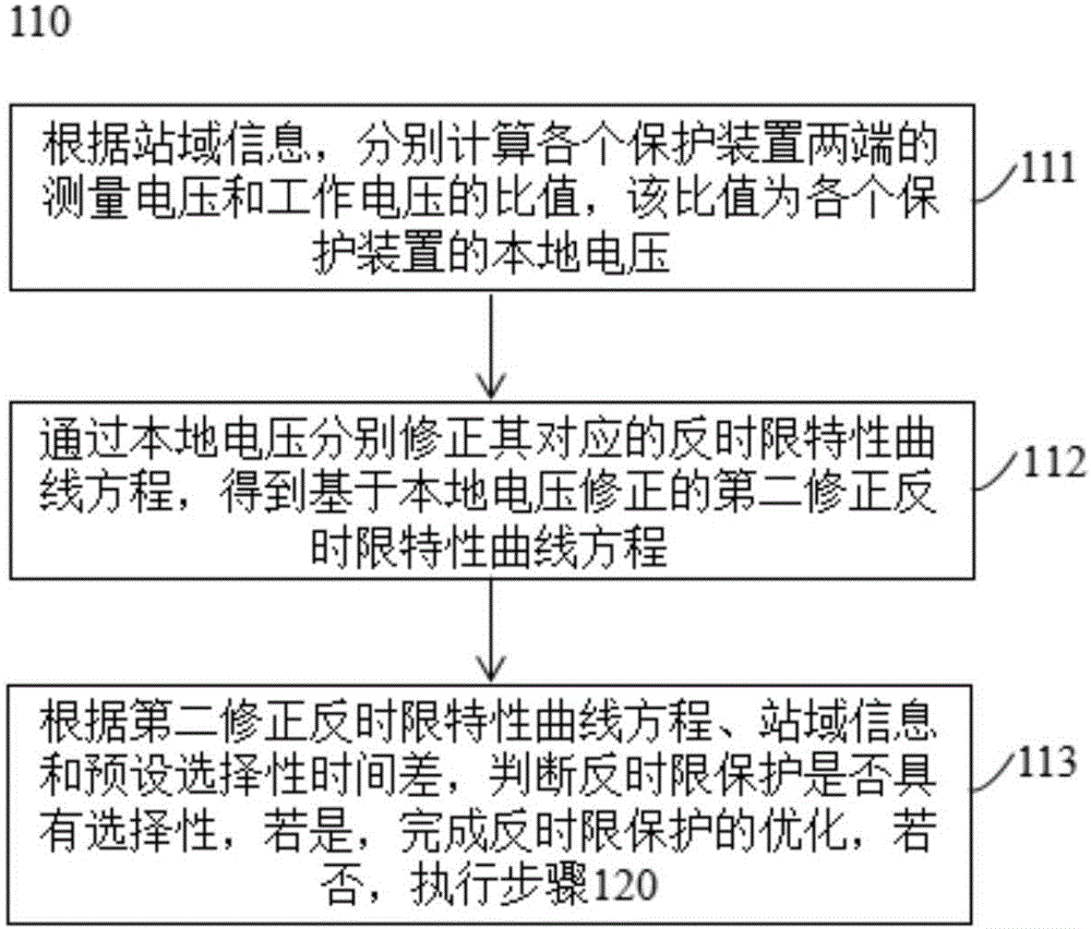
[0066] On the basis of embodiment one or embodiment two, such as figure 2 As shown, step 110 includes:

[0067] Step 111 , according to the station domain information, respectively calculate the ratio between the measured voltage and the working voltage at both ends of each protection device, and the ratio is the local voltage of each protection device.

[0068] Step 112 , respectively modifying the corresponding inverse time-lag characteristic curve equations according to the local voltages to obtain a second modified inverse time-lag characteristic curve equation based on the local voltage correction.

[0069] Step 113 : According to the second modified inverse time lag characteristic curve equation, station domain information and preset selectivity time difference, judge whether the inverse time lag protection is selective, if yes, complete the optimization of the inverse time lag protection, if not, go to step 120 .

[0070] Wherein, the second modified inverse time-lag ...


PUM


Abstract

The invention relates to an inverse time protection optimization method and system. The inverse time protection optimization method comprises the steps that whether inverse time protection in a power grid topological system in which the line fault location is positioned has selectivity is judged according to the station domain information, the inverse time protection curvilinear equation and the preset selective time difference; when the inverse time protection does not have the selectivity, the correction voltage of the high voltage side of the transformer in the power grid topological system is calculated according to the station domain information; the inverse time characteristic curvilinear equation is corrected through the correction voltage of the high voltage side of the transformer and the compensation percentage so as to obtain a first corrected inverse time characteristic curvilinear equation; and the compensation percentage is adjusted according to the first corrected inverse time characteristic curvilinear equation, the station domain information and the preset selective time difference, and the inverse time protection is optimized so that the inverse time protection is enabled to have selectivity and quickness. The inverse time characteristic curvilinear equation is dynamically compensated by using the voltage information of the high voltage side of the transformer based on sharing of the station domain information so that the inverse time protection is enabled to have selectivity and quickness, and thus the method and the system have great practical application value.

Description

technical field [0001] The invention relates to the technical field of relay protection, in particular to an optimization method and system for inverse time-limit protection. Background technique [0002] At this stage, domestic smart substation applications are gradually increasing, but the configuration of protection still inherits the characteristics of traditional relay protection. For each primary device, the main protection with fast tripping and the backup protection with multi-stage coordination are configured, and the protection and related circuits are configured in double sets. completely independent. Judging from the current situation, the protection configuration of the current smart substation does not take advantage of some technical advantages of the smart substation to optimize the backup protection, and there are still inherent defects in the traditional backup protection; the selectivity is guaranteed through the cooperation of fixed value and time, The a...

Claims


Application Information

Patent Timeline
Patent Type & Authority Applications(China)
IPC IPC(8): H02H3/00H02H7/26
CPCH02H3/006H02H7/26
Inventor 林湘宁魏繁荣刘尧金能邢家维李正天
Owner HUAZHONG UNIV OF SCI & TECH
Why Eureka
Try Eureka