
Remote control circuit board test system and method

A testing system and circuit board technology, applied in electronic circuit testing, instruments, measuring electricity, etc., can solve problems such as low testing efficiency, and achieve the effects of improving testing efficiency, improving accuracy, and reducing signal loss

Pending Publication Date: 2017-12-29
JUNSHENG TECH YANGZHOU
View PDF0 Cites 0 Cited by
  • Summary
  • Abstract
  • Description
  • Claims
  • Application Information

AI Technical Summary

Problems solved by technology

[0003] Aiming at the defects in the prior art, the purpose of the present invention is to solve the technical problem of low test efficiency in the prior art, and provide a test system and test method for the circuit board of a remote controller. The present invention has a high degree of automation and can effectively ensure that the test Accuracy, high test efficiency

Method used


Image

  • Remote control circuit board test system and method
  • Remote control circuit board test system and method
  • Remote control circuit board test system and method

Examples


Embodiment Construction

[0027] The present invention will be further described below in conjunction with the accompanying drawings.

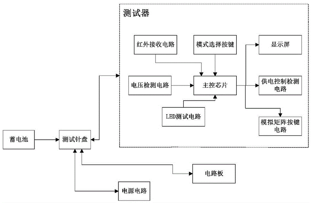
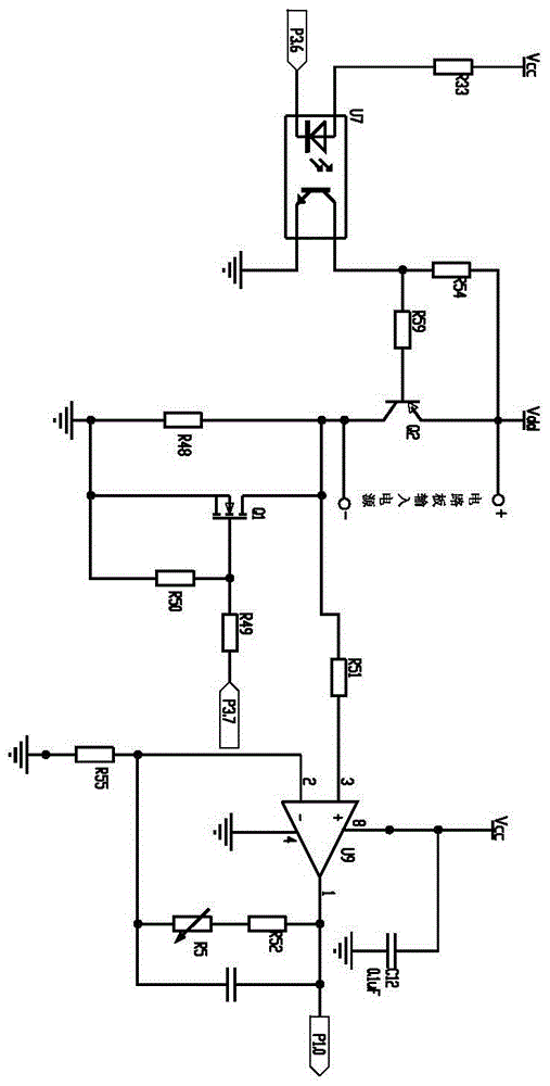
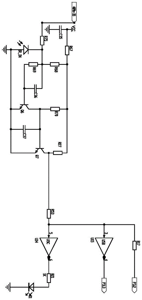
[0028] Such as Figure 1 to Figure 9 A test system for a circuit board of a remote control shown includes a tester, a liftable test dial and several fixed test positioning fixtures for clamping the circuit board. The test dial is provided with several The test points of each circuit board correspond to the test needles one by one. The test needle plate is set directly above the test positioning fixture. The test needle transmits the test signal corresponding to the test point of the circuit board to the tester through the test needle plate. The tester includes the main control Chip U8, power supply circuit, voltage detection circuit, power supply control power consumption detection circuit, alarm circuit, analog matrix button circuit and display screen, power supply circuit for power supply control power consumption detection circuit, alarm circuit, display screen, main ...


PUM


Abstract

The present invention provides a remote control circuit board test system and method, belonging to the remote controller test technology field. The system comprises a tester, a liftable test dial capable and a plurality of fixed test location clamps configured to clamp circuit boards. The test dial is provided with a plurality of testing needles being in one-to-one correspondence with test points of each circuit board, the test dial is arranged above the test location clamps, the testing needles transmit test signals of corresponding test points of the circuit boards to the tester through the test dial, and the tester performs testing of the circuit boards and displays test information of the circuit boards. The remote control circuit board test system and method can test a plurality of circuit boards at the same time, are high in automation degree, can effectively ensure test accuracy and can improve test efficiency.

Description

technical field [0001] The invention relates to a positioning fixture, in particular to a tool for positioning and clamping a PCB board. Background technique [0002] The existing technology uses the product prototype as the standard, reads in its infrared code value and saves it, and then conducts a product test comparison test. Only infrared decoding can be performed, including buttons, current, mode lights, backlights, etc. Manual judgment often results in long operation time and easy misjudgment. The accuracy of the test cannot be guaranteed. One person can only test one product at the same time, and the test efficiency is low. Contents of the invention [0003] Aiming at the defects in the prior art, the purpose of the present invention is to solve the technical problem of low test efficiency in the prior art, and provide a test system and test method for the circuit board of a remote controller. The present invention has a high degree of automation and can effectivel...

Claims


Application Information

Patent Timeline
Patent Type & Authority Applications(China)
IPC IPC(8): G01R31/28
CPCG01R31/2806
Inventor 徐尼军祁鹏飞
Owner JUNSHENG TECH YANGZHOU
Learn More