


Quick Research
Generate reliable direction feasibility study reports for your R&D in just a few steps.

Technical Q&A
Discover and master advanced knowledge NOW. Basics, ideas, possibilities, all at once.

Find Solutions
As an expert in R&D theories, this can generate solutions to your technical problems instantly.

Evaluate Feasibility
Analyze your overall solution with one click, know your potential R&D risks in advance.

Monitor Landscape
Get weekly tech updates, stay abreast of the latest tech innovations and key insights.
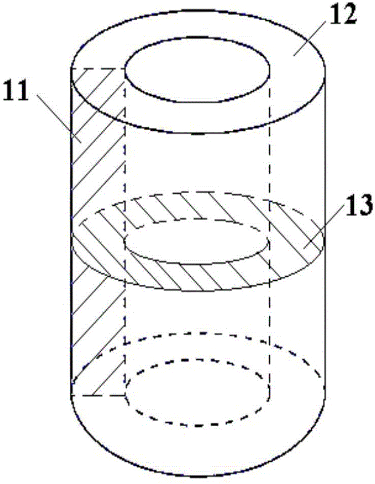
Taylor-Couette experiment device for solid-state medium
An experimental device and medium technology, which is applied in the field of Taylor-Couette experimental devices, can solve the problems of dividing into two or more different types, and cannot realize Taylor-Couette rheological experiments in liquid media, and achieve comprehensive three-dimensional rheology. effect of shape
- Summary
- Abstract
- Description
- Claims
- Application Information
AI Technical Summary
Problems solved by technology
Method used
Image

Examples
Embodiment 1
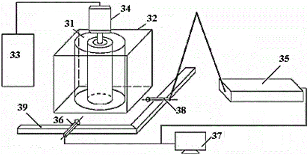
[0086] Use plasticine in two colors, red and blue (corresponding to red Figure 9 Brighter colors in the medium, blue corresponds to Figure 9 The darker color in the middle) was made into a sector-shaped cross-section cylinder with an inner diameter of 20mm, an outer diameter of 32mm, and a height of 10mm, with a central angle of 180°, loaded into the device through the above steps, and connected all parts of the device. Turn on the camera, and the gear ratio used is 2:1, that is, the gear of the transmission part rotates 2 times, and the gear of the main part rotates once. The gear speed of the transmission part is 2 rev / min, the gear speed of the main part is 1 rev / min, and the pressure exerted on the cylindrical plasticine is about 20N. After rotating for different number of turns, the experimental results are shown in Fig. Figure 9 shown.
[0087] At the beginning, the two colors of plasticine were divided into two pieces of two completely different colors. After rota...
Embodiment 2
[0089] Two kinds of materials, lead (Pb) and tin (Sn), are used to make cylinders with an inner diameter of 47mm, an outer diameter of 51mm, and a height of 15mm. The cylinder is equally divided into 4 fan-shaped cross-section columns with a central angle of 90°. Two pieces of lead and two pieces of fan-shaped cross-section cylinders of tin are selected, and the lead and tin are alternately placed to form a cylindrical sample. like Figure 10 shown. Put it into the sample chamber of the Taylor-Couette experimental device of the present invention, use a pressurizing mechanism to pressurize the sample axially by 260KN, and after the inner and outer cylindrical walls of the sample chamber rotate relative to each other for 1 circle, take out the sample, and perform mechanical testing on the cross section of the sample. Grinding and polishing, observe the flow pattern of metal on part of the annular cross section with a microscope, the experimental results are as follows Figure ...
PUM
| Property | Measurement | Unit |
|---|---|---|
| height | aaaaa | aaaaa |
Abstract
Description
Claims
Application Information
 - R&D Engineer
- R&D Manager
- IP Professional
- Industry Leading Data Capabilities
- Powerful AI technology
- Patent DNA Extraction
Browse by: Latest US Patents, China's latest patents, Technical Efficacy Thesaurus, Application Domain, Technology Topic, Popular Technical Reports.
© 2024 PatSnap. All rights reserved.Legal|Privacy policy|Modern Slavery Act Transparency Statement|Sitemap|About US| Contact US: help@patsnap.com