Stuff grinder in waste paper recycling device

A technology of recycling and refining, which is applied in the field of machinery, can solve the problems of non-continuousness, waste of pulp liquid, poor grinding effect, etc., and achieve the effect of improving efficiency and efficiently processing pulp

Pending Publication Date: 2017-12-29
平湖纬宸机械科技有限公司
View PDF0 Cites 1 Cited by
  • Summary
  • Abstract
  • Description
  • Claims
  • Application Information

AI Technical Summary

Problems solved by technology

[0003] At present, in the waste paper repulping production line, the blocky waste paper needs to be broken up by the agitator first, and then the broken paper is transported to the refiner for refining. This process is not continuous, resulting in The efficiency is low; firstly, the refiner grinds a large pile of shredded paper at the same time. Since the shredded paper will be grouped during the grinding process, it will take a long time to completely grind a large pile of shredded paper. As a result, the efficiency is low, and at the same time, there will be more shredded paper that has not been completely ground mixed in the pulp, and the grinding effect is poor; the obtained pulp needs to be treated with ink removal. The current ink removal tank is equipped with a conduit in the middle of the ink tank , the pulp higher than the conduit will flow into the conduit and be exported, and at the same time, the air bubbles on the liquid surface will also be exported, but this structure will also export a lot of pulp liquid, resulting in waste of pulp liquid

Method used


Image

  • Stuff grinder in waste paper recycling device
  • Stuff grinder in waste paper recycling device
  • Stuff grinder in waste paper recycling device

Examples


Embodiment Construction

[0019] The following are specific embodiments of the present invention and in conjunction with the accompanying drawings, the technical solutions of the present invention are further described, but the present invention is not limited to these embodiments.

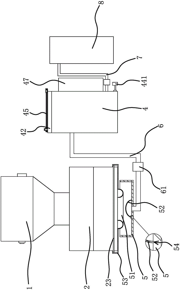
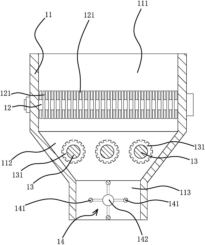
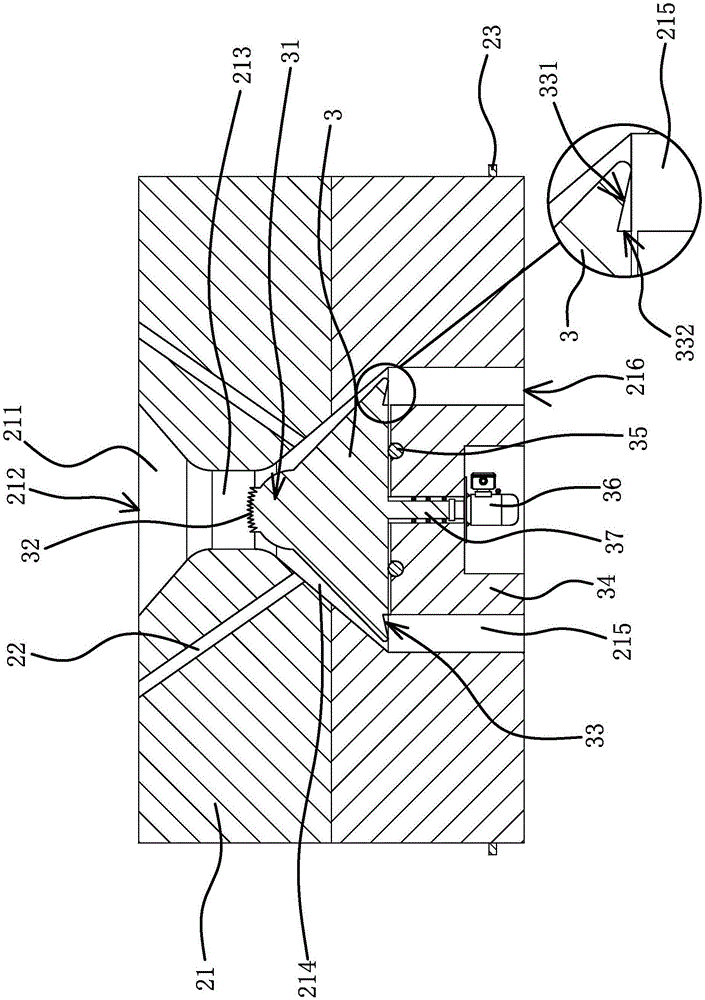
[0020] Such as Figure 1 to Figure 4 As shown, the waste paper recovery treatment device includes a waste paper feed box 1, a refiner 2, an ink removal tank 4 capable of removing ink in the pulp, and a pulp storage tank 8 arranged in sequence. The waste paper feed box 1 is located in the refiner 2, the feed opening of the waste paper feed box 1 is aligned and communicated with the paper inlet 212 of the refiner 2, and the lower end surface of the refiner 2 is provided with a circular slurry outlet 216, and the outlet of the refiner 2 The lower end surface is located at the pulp outlet 216 and is provided with a pulp filtering structure capable of filtering the unground paper. A pipeline 6 is provided between the pulp filte...


PUM


Abstract

The invention provides a stuff grinder in a waste paper recycling device, and belongs to the technical field of machinery. The technical problem that an existing waste paper recycling device is low in pulp processing efficiency is solved. The stuff grinder in the waste paper recycling device comprises a machine body and a grinding head, the machine body is internally provided with a passage, the middle section of the passage is a paper grinding passage, the inner wall of the paper grinding passage is shaped like a circular truncated cone conical surface, the grinding head is located in the paper grinding passage, the grinding head is shaped like a circular truncated cone, the peripheral surface of the grinding head is arranged opposite to the inner wall of the paper grinding passage, the peripheral surface of the grinding head and the inner wall of the paper grinding passage are all rough surfaces, a fixed station is fixed to the portion, located below the paper grinding passage, in the passage, the grinding head is rotationally connected to the fixed station, an annular pulp outlet passage is formed between the fixed station and the inner wall of the passage, multiple water passages are arranged on the machine body, water inlets of the water passages are located in the upper end surface of the machine body, and water outlets of the water passages are located in the inner wall of the paper grinding passage. The stuff grinder has the advantage of being capable of efficiently processing waste paper into pulp.

Description

technical field [0001] The invention belongs to the technical field of machinery, and relates to a waste paper recycling device, in particular to a refiner in the waste paper recycling device. Background technique [0002] Waste paper is usually compressed into cubes after recycling to facilitate transportation, and waste paper will be recycled into pulp for reuse in recycling plants. [0003] At present, in the waste paper repulping production line, the blocky waste paper needs to be broken up by the agitator first, and then the broken paper is transported to the refiner for refining. This process is not continuous, resulting in The efficiency is low; firstly, the refiner grinds a large pile of shredded paper at the same time. Since the shredded paper will be grouped during the grinding process, it will take a long time to completely grind a large pile of shredded paper. As a result, the efficiency is low, and at the same time, there will be more shredded paper that has no...

Claims


Application Information

Patent Timeline
IPC IPC(8): D21B1/32D21B1/34
CPCD21B1/32D21B1/345Y02W30/64
Inventor 赵晨
Owner 平湖纬宸机械科技有限公司
Why Eureka
Try Eureka