Application of tool to controlling feeding lateral perpendicularity of small prisms

A technology for controlling sides and prisms, applied in manufacturing tools, workpiece clamping devices, etc., can solve problems such as product accuracy not meeting drawing requirements, high scrap rate, long turnaround time, etc., to shorten production cycle, reduce production cost, The effect of improving work efficiency

Active Publication Date: 2017-12-29
马鞍山市江南光学有限公司
View PDF7 Cites 4 Cited by
  • Summary
  • Abstract
  • Description
  • Claims
  • Application Information

AI Technical Summary

Problems solved by technology

[0009] Aiming at the problems existing in the prior art that there is no suitable tooling when controlling side sagging of the small prism upper plate, the product precision cannot meet the drawing requirements, the scrap rate is high, and the turnaround time is long. The present invention provides a small prism upper plate control Application of hanging tooling

Method used


Image

  • Application of tool to controlling feeding lateral perpendicularity of small prisms
  • Application of tool to controlling feeding lateral perpendicularity of small prisms

Examples


Embodiment 1

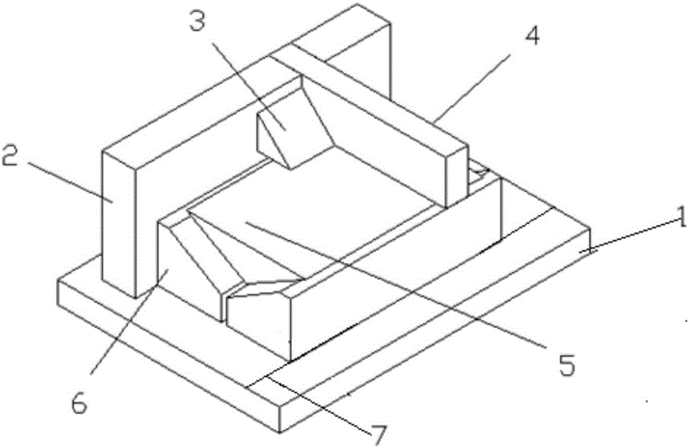
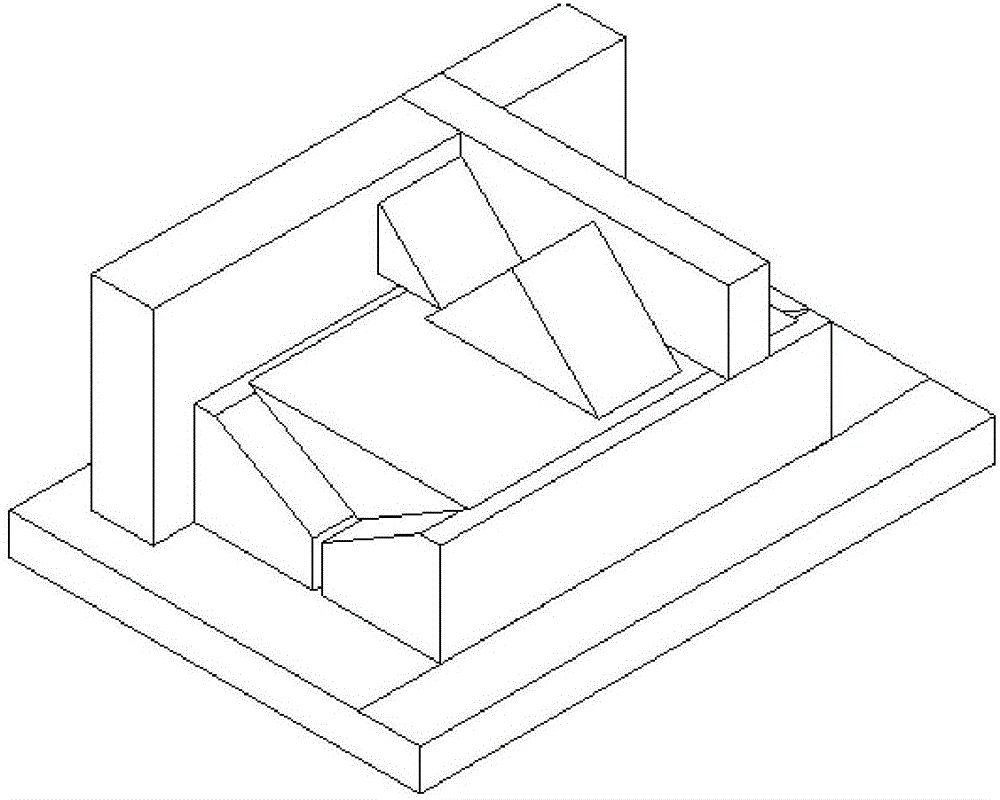
[0036] Such as figure 1As shown, the application of a tooling for controlling side sagging on the small prism upper plate of this embodiment, the tooling for controlling side sagging on the small prism upper plate includes a base 1, a horizontal positioning block 2, a stopper 4 and a horizontal support body 5, and Including V-shaped limit block 6, limit block 3 and positioning marking line 7, wherein base 1, horizontal positioning block 2, stopper 4, limit block 3, horizontal support body 5 and V-shaped limit block 6 are made of Colorless optical glass; the V-shaped limit block 6 is a V-shaped groove structure with an opening angle of 90°, the specification is 160*120*40mm, the tolerance is ±0.01mm, the right angle accuracy is ±30", the bottom surface One side line extends the positioning mark line 7 and the base 1 is glued and fixedly connected with the base 1, and one of the rectangular sides is closely attached to the horizontal positioning block 2, and is lower than the he...

Embodiment 2

[0045] The specific structure of the application of a tooling with a small prism on the plate to control side sagging in this embodiment is basically the same as in embodiment 1, the difference is that it also includes a spirit level; the V-shaped limit block 6 is spliced ​​by two 45 ° triangular prisms to form a 90 ° The V-shaped groove-like structure uses local materials, and there is no need to make special limit blocks, which reduces the production cost.

[0046] In this embodiment, the application of a small prism upper plate to control side sagging is basically the same as that of embodiment 1, the difference is that the entire tooling is calibrated with a spirit level before pasting the small prism.


PUM


Abstract

The invention discloses application of a tool to controlling the feeding lateral perpendicularity of small prisms, ad belongs to the field of technologies for assembling optical components. The tool for controlling the feeding lateral perpendicularity of the small prisms comprises a base, a horizontal positioning block, a check block, a horizontal butting body and a V-shaped limit stopper. The V-shaped limit stopper is of a V-shaped groove-shaped structure with an opening angle of 90 degrees, and the base is of a square panel-shaped structure; the horizontal positioning block is of a cuboid block-shaped structure, a square groove is formed in the horizontal positioning block, and recesses in the shapes of grooves are upwardly vertically arranged on the upper surface of the base in an inverted manner and are close to the edge lines of the base; the check block is of a cuboid block-shaped structure, one end of the check block is fittingly embedded in the groove of the positioning block, and the other end of the check block is vertically arranged on a V-shaped notch of the V-shaped limit stopper; the horizontal butting body is of a 90-degree right-angle triangle structure and is fittingly arranged in a 90-degree V-shaped groove of the V-shaped limit stopper. The application has the advantages that the feeding lateral perpendicularity of small prism products with small dimensional tolerance can be controlled, and the purposes of reducing the scrap rate and improving the work efficiency can be achieved.

Description

[0001] The application of the present invention is a divisional application, the application number of the parent application: 2014108529719; the name of the parent application: a small prism upper plate to control side sagging tooling; the application date of the parent application: 2014-12-31. technical field [0002] The invention relates to the technical field of optical component assembly, in particular to the application of a small prism upper plate to control side sag. Background technique [0003] How to ensure the angular accuracy of the prism in the mass production process is a core problem that must be solved in every process technology solution. Because each process in the manufacturing process may affect the angular accuracy, the control of the angular accuracy runs through the entire manufacturing process, and it also requires a solution to the influencing factors of each process. If this problem cannot be solved well, even with the most advanced processing equ...

Claims


Application Information

Patent Timeline
Patent Type & Authority Applications(China)
IPC IPC(8): B25B11/00
CPCB25B11/00
Inventor 马成
Owner 马鞍山市江南光学有限公司
Why Eureka
Try Eureka