Radiotherapy equipment possessing radiation field boundary identification function

A radiation therapy and boundary technology, which is applied in radiation therapy, treatment, X-ray/γ-ray/particle irradiation therapy, etc., can solve the problem of taking up a lot of space and achieve the effect of saving space

Inactive Publication Date: 2017-12-29
SUZHOU LINATECH MEDICAL SCI & TECH CO LTD
View PDF5 Cites 0 Cited by
  • Summary
  • Abstract
  • Description
  • Claims
  • Application Information

AI Technical Summary

Problems solved by technology

However, it still uses a light reflection projection device, which takes up a lot of space

Method used


Image

  • Radiotherapy equipment possessing radiation field boundary identification function
  • Radiotherapy equipment possessing radiation field boundary identification function
  • Radiotherapy equipment possessing radiation field boundary identification function

Examples


Embodiment Construction

[0022] The present invention will be further described in detail below in conjunction with the accompanying drawings and specific embodiments.

[0023] The object of the present invention is to provide a radiotherapy device with the function of marking the field boundary, which has a small volume, simple and easy-to-use field boundary marking device.

[0024] Radiation therapy equipment includes an accelerator and a field forming device, wherein the field forming device mainly includes a finite light tube, a leaf type grating collimator, and the like.

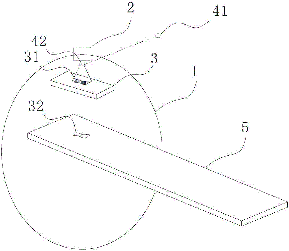
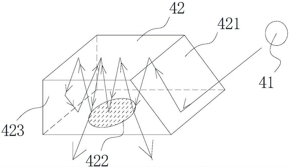
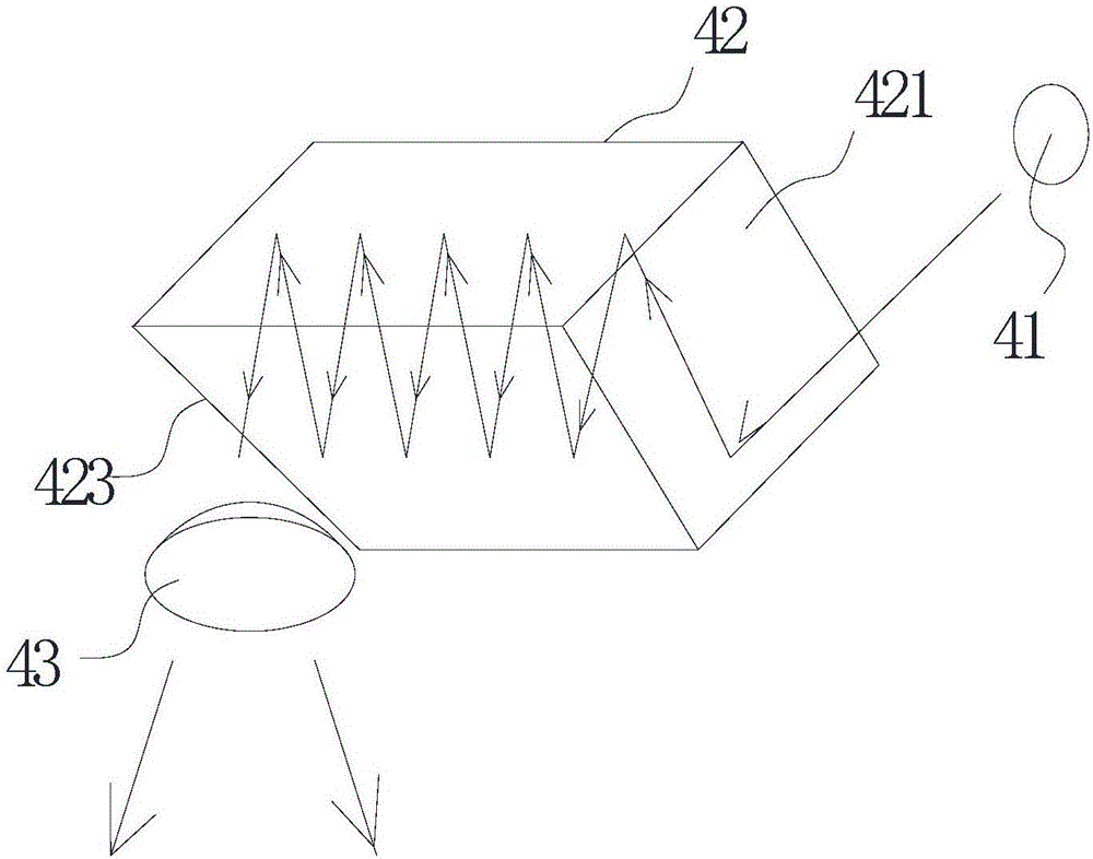
[0025] Such as figure 1 As shown, in order to achieve the above purpose, the technical solution of the present invention is: a radiotherapy equipment with field boundary marking function, including a main frame 1, an accelerator 2 and a field forming device 3, and also includes a field boundary marking device, The field boundary marking device includes a light source 41, and a lens assembly 42 arranged between the accelerator ...


PUM


Abstract

The invention discloses radiotherapy equipment possessing a radiation field boundary identification function. In the invention, a lens component is used to replace a reflection apparatus and an external light source can select a light source with a small diameter light beam, such as a laser light source, an LED spot light source and the like. The lens component possesses a beam expanding effect and the size of the lens component can be smaller than that of the reflection apparatus in the prior art so that a space occupied by the reflection apparatus can be effectively saved.

Description

technical field [0001] The invention relates to an accelerator therapy device, in particular to a radiation therapy device for radiation therapy with the function of marking the field boundary. Background technique [0002] With the development of tumor radiology and material science, as an important means of cancer treatment, radiotherapy has gradually entered the era of "three precisions" of precise positioning, precise planning and precise treatment. Among them, it is necessary to confirm the shape and position of the radiation field before treatment, so that the patient can be positioned and the radiation field adjustment device (such as a collimator, etc.) can be adjusted. The light passes through field control devices such as collimators or light-limiting tubes, and projects the outline of the field on the patient or phantom, and also determines the position of the field. For example, CN103212164A discloses a method for calibrating the radiation field / simulated light ...

Claims


Application Information

Patent Timeline
Patent Type & Authority Applications(China)
IPC IPC(8): A61N5/10
CPCA61N5/1042A61N5/1049A61N2005/105A61N2005/1056
Inventor 姚毅
Owner SUZHOU LINATECH MEDICAL SCI & TECH CO LTD
Why Eureka
Try Eureka