Radiotherapy equipment with radiation field boundary identifying function

A radiation therapy and boundary technology, which is applied in radiation therapy, treatment, X-ray/γ-ray/particle irradiation therapy, etc., can solve the problem of large space occupation, and achieve the effect of reducing height and size

Inactive Publication Date: 2017-12-26
SUZHOU LINATECH MEDICAL SCI & TECH CO LTD
View PDF6 Cites 0 Cited by
  • Summary
  • Abstract
  • Description
  • Claims
  • Application Information

AI Technical Summary

Problems solved by technology

However, it still uses a light reflection projection device, which takes up a lot of space

Method used


Image

  • Radiotherapy equipment with radiation field boundary identifying function
  • Radiotherapy equipment with radiation field boundary identifying function
  • Radiotherapy equipment with radiation field boundary identifying function

Examples


Embodiment Construction

[0022] The present invention will be further described in detail below in conjunction with the accompanying drawings and specific embodiments.

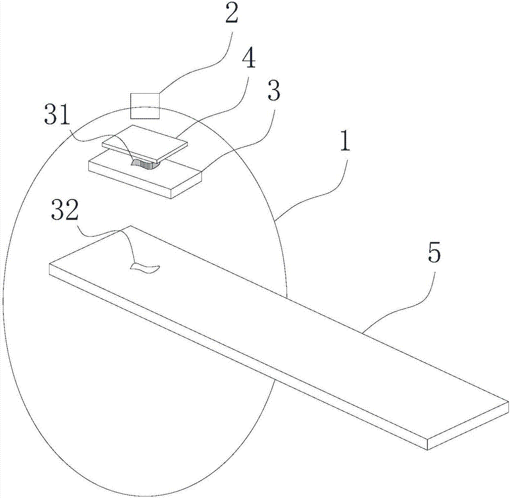
[0023] Such as figure 1 As shown, a radiotherapy device with field boundary marking function includes a main frame 1, an accelerator 2, a field forming device 3, and a field boundary marking device. Fields form light emitting means 4 between means 3 .

[0024] Among them, the radiation field forming device 3 mainly includes a finite light tube, a leaf-type grating collimator, and the like.

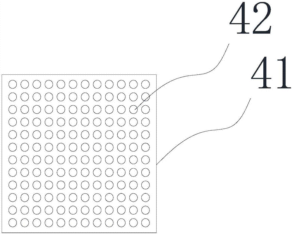
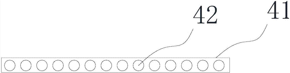
[0025] In the invention, the light-emitting device is directly installed between the accelerator and the radiation field forming device, and the light-reflecting device and the external light source are canceled. The light-emitting device can be flattened, which can greatly reduce the height dimension of the field boundary marking device on the ray axis. In the prior art, because the reflective device must have a little angle to re-change the di...


PUM


Abstract

The invention discloses radiotherapy equipment with a radiation field boundary identifying function. A light-emitting device is directly mounted between an accelerator and a radiation field forming device, and a light-reflecting device and an external light source are omitted. The light-emitting device can be flattened, so that the height dimension of a radiation field boundary identifying device in the axial direction of rays can be decreased greatly. In the prior art, the light-reflecting device must have a certain angle to re-change light directions, so that it is difficult to reduce the dimension in the axial direction of the rays. By the radiotherapy equipment, the problem can be well solved. Existing light-emitting elements, such as LED light sources and laser generators, are thinner and miniaturized, so that low weight and thinness requirements can be met; parallel light sources can be produced, and related technical requirements can be met.

Description

technical field [0001] The invention relates to an accelerator therapy device, in particular to a radiation therapy device for radiation therapy with the function of marking the field boundary. Background technique [0002] With the development of tumor radiology and material science, as an important means of cancer treatment, radiotherapy has gradually entered the era of "three precisions" of precise positioning, precise planning and precise treatment. Among them, it is necessary to confirm the shape and position of the radiation field before treatment, so that the patient can be positioned and the radiation field adjustment device (such as a collimator, etc.) can be adjusted. The light passes through field control devices such as collimators or light-limiting tubes, and projects the outline of the field on the patient or phantom, and also determines the position of the field. For example, CN103212164A discloses a method for calibrating the radiation field / simulated light ...

Claims


Application Information

Patent Timeline
IPC IPC(8): A61N5/10
CPCA61N5/1028A61N5/1045A61N5/1065A61N2005/1092A61N2005/1097A61N2005/1022
Inventor 姚毅
Owner SUZHOU LINATECH MEDICAL SCI & TECH CO LTD
Why Eureka
Try Eureka