Infusion alarming system
An alarm system and output technology, applied in control/regulation systems, flow monitors, flow control, etc., can solve the problems of complex processing circuits, high costs, and no practical significance, and achieve the effect of avoiding liquid pollution
- Summary
- Abstract
- Description
- Claims
- Application Information
AI Technical Summary
Problems solved by technology
Method used
Image
Examples
Embodiment 1
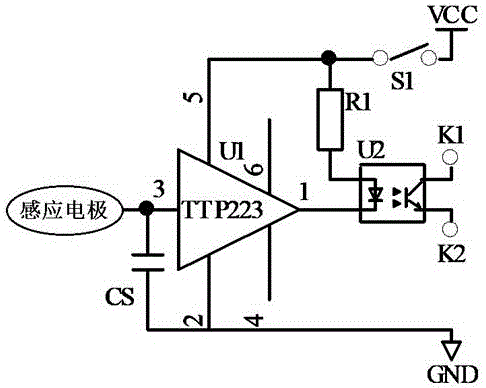
[0020] Such as figure 1 Shown: an infusion alarm system, including batteries, sensing electrodes, touch integrated circuit U1, photocoupler U2 and resistor R1. Wherein, the working voltage of the battery is 3-5V, which can be a button battery of 3V or a lithium battery of 4.2V. The touch integrated circuit U1 is a single-key touch sensor chip TTP223. The specific connection relationship of each component is as follows:
[0021] The positive pole VCC of the battery is connected to one end of the power switch S1, and the other end of the power switch S1 is connected to pin 5 of the power input terminal of the touch integrated circuit U1. At the same time, the photocoupler U2 is also connected to pin 5 of the touch integrated circuit U1 through the resistor R1. The touch input terminal 3 of the touch integrated circuit U1 is connected to the sensing electrode, and the sensing electrode can be a thin metal sheet with an area of not less than 0.3 cm² or a copper-clad PCB. A c...
Embodiment 2
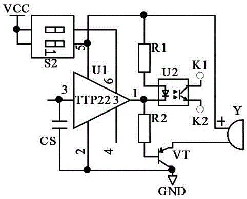
[0026] Such as figure 2 Shown: an infusion alarm system, including sensing electrodes, batteries, touch integrated circuit U1, photocoupler U2, resistors R1 and R2, 2-bit dial switch S2, triode VT and buzzer Y. Wherein, the working voltage of the battery is 3-5V, which can be a button battery of 3V or a lithium battery of 4.2V. The touch integrated circuit U1 is a TTP223 chip. The transistor VT is a PNP transistor. Buzzer Y is an active buzzer. The specific connection relationship of each component is as follows:
[0027] After the first and second ends of the 2-digit DIP switch S2 are connected together, they are connected to the positive pole VCC of the battery; the first switch at the other end of the 2-digit DIP switch S2 is connected to the touch IC U1. 5 feet. The second switch of the 2-bit dial switch S2 is connected to pin 6 of the touch integrated circuit U1, and pin 6 is a mode selection terminal.
[0028] The anode of the primary infrared emitting tube of the...
PUM
 Abstract
Description
Claims
Application Information
 - R&D Engineer
- R&D Manager
- IP Professional
- Industry Leading Data Capabilities
- Powerful AI technology
- Patent DNA Extraction
Browse by: Latest US Patents, China's latest patents, Technical Efficacy Thesaurus, Application Domain, Technology Topic, Popular Technical Reports.
© 2024 PatSnap. All rights reserved.Legal|Privacy policy|Modern Slavery Act Transparency Statement|Sitemap|About US| Contact US: help@patsnap.com


