An antenna structure of a mobile terminal and the mobile terminal

A mobile terminal and antenna structure technology, which is applied in the field of communication, can solve the problems of limited antenna wiring range, small distance between the antenna radiation piece and the reference ground, etc., and achieve the effect of increasing the wiring area and improving the radiation performance

Active Publication Date: 2020-04-10
VIVO MOBILE COMM CO LTD
View PDF8 Cites 0 Cited by
  • Summary
  • Abstract
  • Description
  • Claims
  • Application Information

AI Technical Summary

Problems solved by technology

[0004] Embodiments of the present invention provide an antenna structure for a mobile terminal and a mobile terminal to solve the problem that the antenna layout in the prior art has a small distance between the antenna radiation piece and the reference ground, and the antenna wiring range is limited. question

Method used


Image

  • An antenna structure of a mobile terminal and the mobile terminal
  • An antenna structure of a mobile terminal and the mobile terminal

Examples


Embodiment Construction

[0014] The following will clearly and completely describe the technical solutions in the embodiments of the present invention with reference to the accompanying drawings in the embodiments of the present invention. Obviously, the described embodiments are some of the embodiments of the present invention, but not all of them. Based on the embodiments of the present invention, all other embodiments obtained by persons of ordinary skill in the art without creative efforts fall within the protection scope of the present invention.

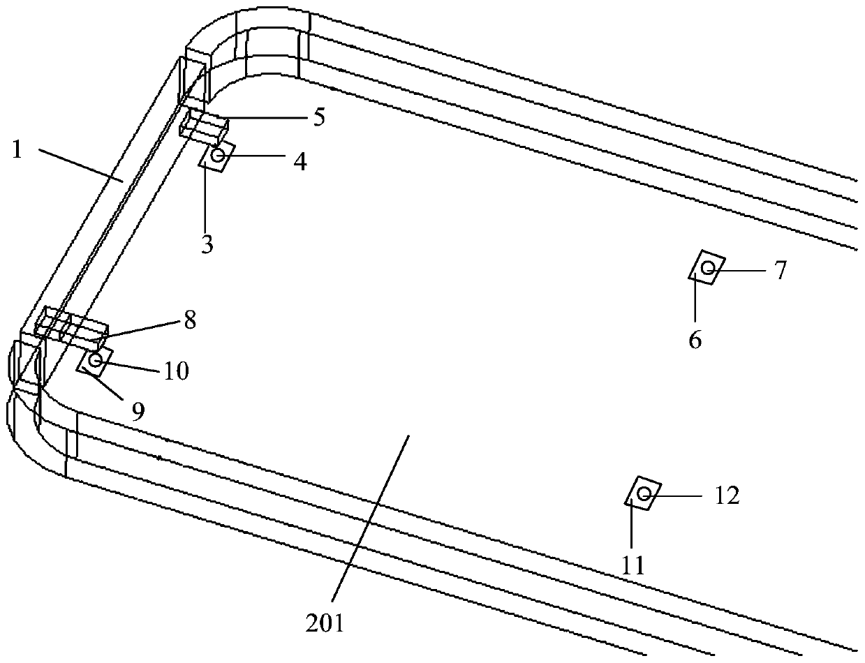
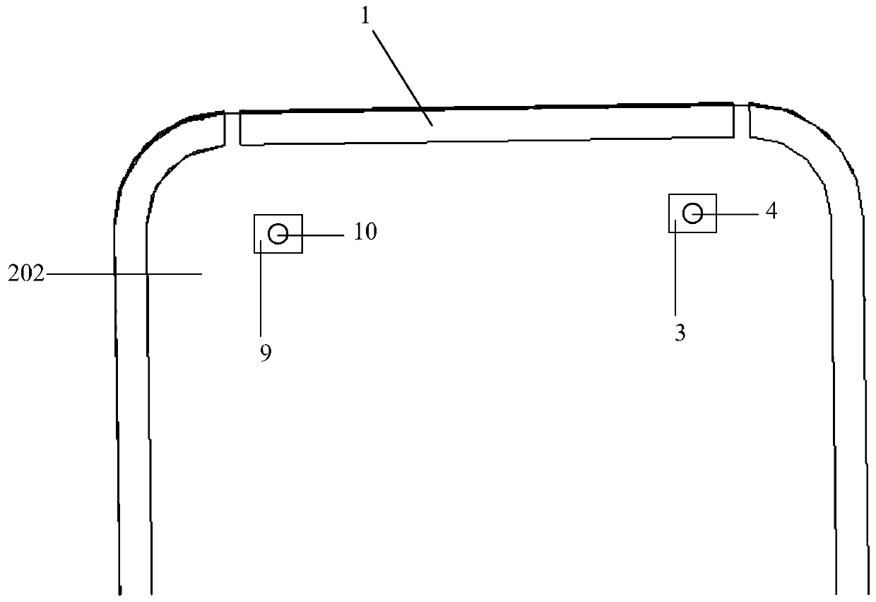
[0015] Embodiments of the present invention provide an antenna structure for a mobile terminal, such as figure 1 with figure 2 As shown, the antenna structure of the mobile terminal includes:

[0016] The antenna radiator 1, the antenna radiator 1 is located on the inner surface 201 of the insulating battery cover of the mobile terminal, the antenna radiator 1 is provided with at least one feed connection point and at least one ground connection poin...


PUM


Abstract

The invention provides an antenna structure of a mobile terminal and the mobile terminal. The antenna structure of the mobile terminal comprises an antenna radiator and a first antenna wiring, wherein the antenna radiator is located on an inner surface of an insulation cell cover of the mobile terminal; the antenna radiator is provided with at least one feed connection point and at least one grounding connection point; the feed connection point is electrically connected to a feed end arranged on a circuit main board of the mobile terminal; and the circuit main board is located on the inner surface of the insulation cell cover; and the first antenna wiring is arranged on an outer surface of the insulation cell cover; the insulation cell cover is provided with a first through hole and a second through hole; one end of the first antenna wiring passes through the first through hole and then is electrically connected to the grounding connection point; and the other end of the first antenna wiring passes through the second through hole and then is electrically connected to a ground end arranged on the circuit main board. In the scheme of the invention, problems that a distance between an antenna radiation sheet and reference ground is small and a range of the antenna wiring is limited are solved.

Description

technical field [0001] The present invention relates to the field of communication technology, and in particular to an antenna structure of a mobile terminal and the mobile terminal. Background technique [0002] The current design of mobile terminals is becoming thinner and thinner, resulting in a reduction in the distance between the antenna radiation piece and the reference ground. At the same time, product reliability design requirements are getting higher and higher, such as: waterproof, salt spray, drop, etc., so the terminal structure design will produce corresponding buttons, waterproof foam, etc., and the antenna area should also be equipped with USB, speakers, microphones, etc. Headphones and other devices. However, in the prior art, the antenna wiring is arranged inside the battery cover, so that the structural design of the terminal and other devices in the antenna area will restrict the layout of the antenna wiring, thereby affecting the radiation performance o...

Claims


Application Information

Patent Timeline
Patent Type & Authority Patents(China)
IPC IPC(8): H01Q1/50
CPCH01Q1/50
Inventor 姚明侯梓鹏马超伟张声陆
Owner VIVO MOBILE COMM CO LTD
Why Eureka
Try Eureka