Mechanical arm monitoring system and method
A technology of robotic arms and monitoring systems, applied in the manufacture of electrical components, semiconductor/solid-state devices, circuits, etc., can solve problems such as mechanical aging, damage to other workpieces, and component damage, and achieve the effect of safely picking and placing substrates
- Summary
- Abstract
- Description
- Claims
- Application Information
AI Technical Summary
Problems solved by technology
Method used
Image
Examples
Embodiment 1
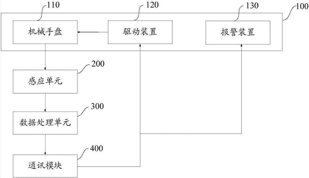
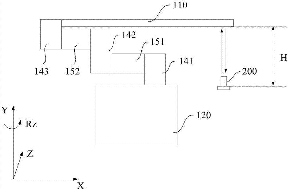
[0051] figure 1 It is a schematic diagram of the principle of the monitoring system of the robotic arm in Embodiment 1 of the present invention, figure 2 It is a schematic structural diagram of the monitoring system of the robotic arm in Embodiment 1 of the present invention, combined with figure 1 and figure 2 As shown, the robot arm 100 has a robot plate 110 for carrying substrates. Apparently, when the precision of the robot arm 100 is abnormal, the position of the manipulator plate 110 will be affected correspondingly, and then when the manipulator plate 110 picks and places the substrate, it is very easy to scratch the substrate. Therefore, the present invention utilizes a The monitoring system monitors the position of the manipulator plate 110 to reflect the positioning accuracy of the manipulator 100 . In the monitoring system of this embodiment, the position information of the manipulator plate 110 is obtained through a sensing unit 200, and the position information...
Embodiment 2
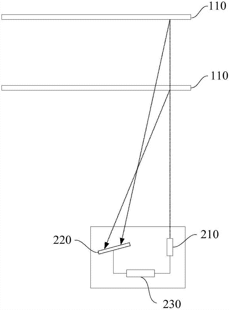
[0064] Figure 4 It is a schematic structural diagram of the monitoring system of the robotic arm in Embodiment 2 of the present invention, as Figure 4 and combine figure 1 As shown, the difference from Embodiment 1 is that in this embodiment, the sensing unit 200' is used to detect whether there is a manipulator disc 110 in its sensing area, wherein the sensing area of the sensing unit 200' is the manipulator disc 110 area of predetermined location. That is, when the sensing unit 200' does not detect the manipulator disc 110, it means that there is a deviation in the position of the manipulator disc 110; when the sensing unit 200' detects the manipulator disc 110, it means that there is no position deviation , the precision of the robotic arm is normal, and production operations can continue.
[0065] Specifically, the sensing unit 200' can adopt an optical fiber sensor, which includes a transmitting part 210' and a receiving part 220', the transmitting part 210' is u...
Embodiment 3
[0068] In addition, according to the above-mentioned monitoring system of the robotic arm, the present invention also provides a monitoring method of the robotic arm. Figure 5 It is a schematic flow chart of the monitoring method of the robotic arm in Embodiment 1 of the present invention, refer to Figure 5 and combine figure 1 As shown, the monitoring method includes:
[0069] S10, providing a mechanical arm, the mechanical arm includes a mechanical hand plate;
[0070] S20, using a sensing unit to acquire position information of the manipulator disc, and sending the position information of the manipulator disc to a data processing unit;
[0071] S30, using the data processing unit to determine whether there is a deviation in the position of the manipulator disc.
[0072] Wherein, in step S20-S30, can refer to Figure 6a A method for judging the position deviation of the manipulator disc is shown. That is, in step S20, the method for the sensing unit to acquire the pos...
PUM
 Abstract
Description
Claims
Application Information
 - R&D
- Intellectual Property
- Life Sciences
- Materials
- Tech Scout
- Unparalleled Data Quality
- Higher Quality Content
- 60% Fewer Hallucinations
Browse by: Latest US Patents, China's latest patents, Technical Efficacy Thesaurus, Application Domain, Technology Topic, Popular Technical Reports.
© 2025 PatSnap. All rights reserved.Legal|Privacy policy|Modern Slavery Act Transparency Statement|Sitemap|About US| Contact US: help@patsnap.com


