A positioning device and positioning method for numerically controlled cutting of steel plates

A technology of positioning device and steel plate, applied in auxiliary devices, welding/cutting auxiliary equipment, welding/welding/cutting items, etc., can solve the problems of small cutting allowance, poor positioning accuracy, and non-coiled delivery, etc., and achieve simple operation. , the effect of high positioning accuracy

Active Publication Date: 2021-12-31
SINOHYRDO ENG BUREAU 3 CO LTD
View PDF6 Cites 0 Cited by
  • Summary
  • Abstract
  • Description
  • Claims
  • Application Information

AI Technical Summary

Problems solved by technology

[0002] The raw steel plates for the existing pressure steel pipes are all made of cut-to-length steel plates. The cut-to-length steel plates refer to the width greater than or equal to 150mm, and the thickness is usually greater than 4mm. Generally, they are delivered in straight strips, not in coils. For water chestnut steel, in the process of cutting steel plates to length, in order to ensure the roundness of assembled steel pipes after rolling, the cutting allowance is required to be small, and the cutting error is not greater than 2mm, which requires high precision. The positioning method is as follows: before each steel plate cutting, the operator uses a tape measure to measure the distance between the edge of the steel plate to be cut and the track of the cutting machine, and multiple adjustments are required. The positioning construction efficiency is low and the positioning accuracy is poor.

Method used


Image

  • A positioning device and positioning method for numerically controlled cutting of steel plates
  • A positioning device and positioning method for numerically controlled cutting of steel plates
  • A positioning device and positioning method for numerically controlled cutting of steel plates

Examples


Embodiment Construction

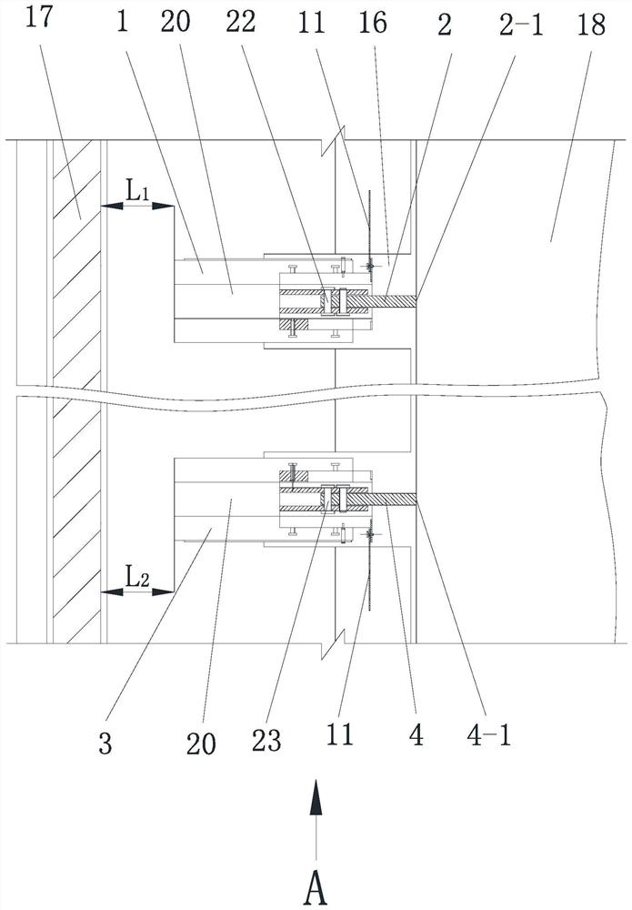
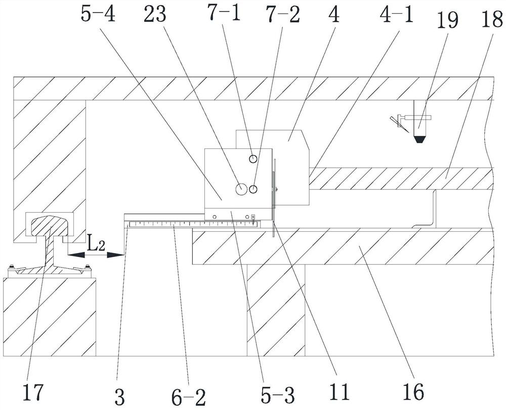
[0056] Such as Figure 1 to Figure 5 and Figure 7 The shown positioning device for numerically controlled cutting of steel plates includes a first positioning mechanism and a second positioning mechanism that are installed on the operating platform 16 of the cutting machine and position the steel plate 18 to be cut. The second positioning mechanism is located on the same side of the steel plate 18 to be cut;

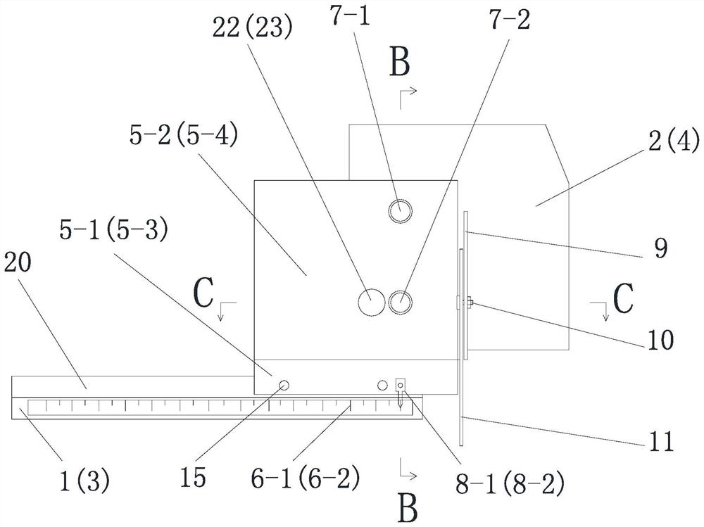
[0057] The first positioning mechanism includes a first base plate 1, a first sliding seat installed on the first base plate 1 and capable of sliding along the length direction of the first base plate 1, and a first sliding seat installed on the first base plate and to be cut. The first positioning plate 2 for positioning the steel plate 18;

[0058] The second positioning mechanism includes a second base plate 3, a second sliding seat that is installed on the second base plate 3 and can slide along the length direction of the second base plate 3, and is installed on ...


PUM


Abstract

The invention discloses a positioning device for numerically controlled cutting of steel plates, comprising a first positioning mechanism and a second positioning mechanism installed on an operation platform to position the steel plate to be cut, the first positioning mechanism and the second positioning mechanism are positioned on the on the same side; the first positioning mechanism includes a first bottom plate, a first sliding seat installed on the first bottom plate, and a first positioning plate installed on the first sliding seat and positioning the steel plate to be cut. The invention discloses a positioning method, comprising: 1. adjustment of the first bottom plate and the second bottom plate; 2. adjustment of the first sliding seat and the second sliding seat; 3. positioning of the steel plate to be cut; 4. CNC cutting of cutting steel plates. The positioning device of the present invention does not require repeated measurement and multiple adjustments by the operator, and can prevent chips or splashes from adversely affecting the positioning accuracy of the first positioning plate or the second positioning plate. The positioning method of the present invention can effectively improve the positioning work. efficiency and positioning accuracy.

Description

technical field [0001] The invention belongs to the technical field of steel plate cutting, and in particular relates to a positioning device and a positioning method for numerically controlled cutting of steel plates. Background technique [0002] The raw steel plates for the existing pressure steel pipes are all made of cut-to-length steel plates. The cut-to-length steel plates refer to the width greater than or equal to 150mm, and the thickness is usually greater than 4mm. Generally, they are delivered in straight strips, not in coils. For water chestnut steel, in the process of cutting steel plates to length, in order to ensure the roundness of assembled steel pipes after rolling, the cutting allowance is required to be small, and the cutting error is not greater than 2mm, which requires high precision. The positioning method is as follows: before each steel plate cutting, the operator uses a tape measure to measure the distance between the edge of the steel plate to be ...

Claims


Application Information

Patent Timeline
Patent Type & Authority Patents(China)
IPC IPC(8): B23K37/04B23K37/00B23K101/18
Inventor 杨联东盛连才屈刚杨建军
Owner SINOHYRDO ENG BUREAU 3 CO LTD
Why Eureka
Try Eureka