Surgical Robot Adjustment System
A surgical robot and adjustment system technology, applied in the field of surgical robot adjustment system, can solve the problems of lower positioning accuracy of the mechanical arm, error accumulation, and influence on the robot control accuracy, so as to improve motion control accuracy, prevent collisions, and increase the success rate of surgery Effect
- Summary
- Abstract
- Description
- Claims
- Application Information
AI Technical Summary
Problems solved by technology
Method used
Image
Examples
Embodiment 1
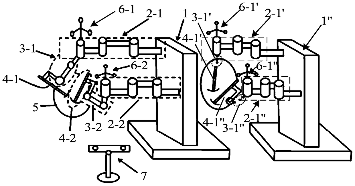
[0039] Please refer to figure 2 , figure 2 It is a schematic diagram of the structure of the surgical robot adjustment system when the optical target mirror is arranged at the end of the adjustment arm in Embodiment 1 of the present invention. like figure 2 As shown, the surgical robot adjustment system includes: a base 1 and at least one mechanical arm fixed on the base 1, and each of the mechanical arms includes adjustment arms connected in sequence (marked as 2-1, 2 in the figure -2), active arm (labeled as 3-1, 3-2 in the figure) and surgical instrument arm (labeled as 4-1, 4-2 in the figure), the adjustment arm is connected with the base 1, compared The surgical robot adjustment system of the prior art, the surgical robot adjustment system of the present invention also includes a calculation module, an optical tracking system, and the optical tracking system includes an optical target mirror (marked as 6-1, 6-2 in the figure) and an optical tracking system. instrume...
Embodiment 2
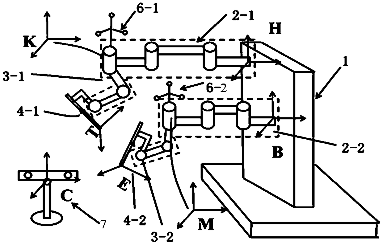
[0073] Please refer to image 3 , which is a structural schematic diagram of the surgical robot adjustment system when the optical target mirror is set on the active arm in the second embodiment of the present invention. to combine image 3 and figure 2 Comparative analysis shows that, image 3 and figure 2 The difference lies in the specific positions of the four optical target mirrors on the mechanical arm, figure 2 The four optical target mirrors are all set at the end of the adjustment arm, and image 3 The four optical target mirrors are all set on the active arm, so the image 3 The number of sensors required for the adjustment system of the surgical robot shown will be reduced, which reduces the consumption of material resources, reduces costs, and improves the positioning accuracy of the mechanical arm. Specifically, such as image 3As shown, the optical target mirror 6-2 is arranged on the arm between the first node and the second node of the active arm 3-2,...
Embodiment 3
[0076] Please refer to Figure 4 , which is a structural schematic diagram of the surgical robot adjustment system when the optical target mirror is set on the end of the active arm and the adjustment arm in the third embodiment of the present invention. Compared with the structure described in Embodiment 1 and Embodiment 2, the difference is that the optical target mirror 6-1 is placed on the arm between the first node and the second node of the active arm 3-1, and the optical target mirror 6-2 As for the joint of the active arm 3-2 and the adjustment arm 2-2, another optical target mirror is as for the joint of the active arm and the adjustment arm. equivalent to figure 2 and image 3 The fusion of the position of the optical target mirror on the mechanical arm, that is, the optical target mirror is set on both the adjustment arm and the active arm. In addition, the number of bases of the surgical robot adjustment system and the number of mechanical arms arranged on each...
PUM
 Abstract
Description
Claims
Application Information
 - R&D
- Intellectual Property
- Life Sciences
- Materials
- Tech Scout
- Unparalleled Data Quality
- Higher Quality Content
- 60% Fewer Hallucinations
Browse by: Latest US Patents, China's latest patents, Technical Efficacy Thesaurus, Application Domain, Technology Topic, Popular Technical Reports.
© 2025 PatSnap. All rights reserved.Legal|Privacy policy|Modern Slavery Act Transparency Statement|Sitemap|About US| Contact US: help@patsnap.com


