Position-adjustable metal plate punching mechanism

A sheet metal, adjustable technology, applied in the field of hardware parts manufacturing equipment, can solve the problems of clamping device thickness requirements, large cutting impact, complex clamping mechanism, etc., to achieve lower installation accuracy requirements, firm and convenient clamping, The effect of simple structure

Inactive Publication Date: 2017-12-26
FOSHAN RUIPUDA OPTOELECTRONICS TECH CO LTD
View PDF0 Cites 20 Cited by
  • Summary
  • Abstract
  • Description
  • Claims
  • Application Information

AI Technical Summary

Problems solved by technology

[0002] The sheet metal cutting mechanism of existing large-scale machining units is generally clamped by a clamping mechanism, and then cut off by an oil cylinder. It is generally suitable for large-volume sheet metal processing. The clamping mechanism is complicated and the cutting impact is large. For thin The cutting of small-volume metal sheets is not ideal, power consumption, and the thickness of the clamping device is required, so it cannot clamp thin sheets
[0003] Moreover, the height of the plate placement plate of the existing plate cutting mechanism is fixed, and cannot be adjusted according to the needs, so that when other parts clamp the steel plate and transport it, it is necessary to ensure accurate cooperation, which greatly increases the difficulty of installation. high equipment requirements

Method used


Image

  • Position-adjustable metal plate punching mechanism

Examples


Embodiment

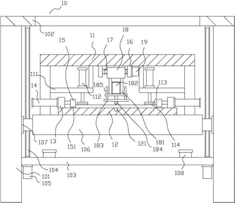
[0017] Example: see figure 1 As shown, a position-adjustable sheet metal punching mechanism includes a frame 10, and the frame 10 includes two main vertical plates 101 and a main top plate 102, and the top ends of the two main vertical plates 101 are fixed on the main On both sides of the bottom surface of the top plate 102, the lower middle plate 103 is fixed on the inner side walls of the two main vertical plates 101, and the two main vertical screw rods 104 are on both sides of the lower middle plate 103, and the bottom ends of the main vertical screw rods 104 are hinged On the lower middle plate 103, the top of the main vertical screw 104 is hinged on the bottom surface of the main top plate 102, and two main adjustment motors 105 are fixed on both sides of the lower middle plate 103, and the output shafts of the main adjustment motors 105 are spline shafts , the spline shaft is inserted into the spline hole at the bottom of the main vertical screw rod 104, the main moving...


PUM


Abstract

The invention discloses a position-adjustable metal plate punching mechanism, which includes a frame. The frame includes two main vertical plates and a main top plate. The top ends of the two main vertical plates are fixed on both sides of the bottom surface of the main top plate. side, the lower middle plate is fixed on the inner side walls of the two main vertical plates, the two main vertical screws are on both sides of the lower middle plate, the bottom ends of the main vertical screws are hinged on the lower middle plate, the main vertical screws The top of the main adjustment motor is hinged on the bottom surface of the main top plate, and the two main adjustment motors are fixed on both sides of the lower middle plate. The output shaft of the main adjustment motor is a spline shaft, and the spline shaft is inserted into the bottom of the main vertical screw. It is in the spline hole; it has simple structure, firm and convenient clamping, convenient punching, and is suitable for thin and small-volume sheet materials, and it can adjust the height position of the main moving plate, so as to ensure that it is compatible with the height of the conveying mechanism, so that The installation accuracy requirements are greatly reduced, and the installation is convenient.

Description

Technical field: [0001] The invention relates to the technical field of hardware component manufacturing equipment, and more specifically relates to a position-adjustable metal plate punching mechanism. Background technique: [0002] The sheet metal cutting mechanism of existing large-scale machining units is generally clamped by a clamping mechanism, and then cut off by an oil cylinder. It is generally suitable for large-volume sheet metal processing. The clamping mechanism is complicated and the cutting impact is large. For thin The cutting of small-volume metal sheets is not ideal, consumes power, and the thickness of the clamping device is required, so it cannot clamp thin sheets. [0003] Moreover, the height of the plate placement plate of the existing plate cutting mechanism is fixed, and cannot be adjusted according to the needs, so that when other parts clamp the steel plate and transport it, it is necessary to ensure accurate cooperation, which greatly increases th...

Claims


Application Information

Patent Timeline
IPC IPC(8): B21D28/02B21D28/14B21D28/04
CPCB21D28/02B21D28/04B21D28/14
Inventor 叶青
Owner FOSHAN RUIPUDA OPTOELECTRONICS TECH CO LTD
Why Eureka
Try Eureka