Wireless sensor network capable of being remotely charged in wireless mode

A wireless sensor, long-range wireless technology, applied in network topology, wireless communication, electrical components, etc., can solve the problems of large size, non-recyclability, limited energy supply life, etc., to achieve high transmission efficiency, solve energy supply difficulties, and low cost Effect

Inactive Publication Date: 2017-12-22
王翔
View PDF0 Cites 3 Cited by
  • Summary
  • Abstract
  • Description
  • Claims
  • Application Information

AI Technical Summary

Problems solved by technology

[0003] Although the application prospect of wireless sensor network is very bright, the power supply method has become a major problem restricting its development.
Generally, batteries are used to supply power to various micro devices, but traditional batteries have some irreversible energy supply defects: large size, high quality, limited energy supply life, and repeated charging when energy is exhausted; at the same time, in many wireless sensor networks, Using and replacing batteries, even long-life ones, is impractical because sensor nodes are often installed in non-recyclable locations, and the effort and cost of replacing hundreds of batteries is prohibitive
[0004] Wireless charging energy supply becomes particularly important for wireless sensor networks, and many current wireless charging methods are short-distance charging, and wireless sensor networks are generally far away from the charging source, so short-distance charging cannot be performed, and the purpose of charging cannot be achieved. Need to realize remote wireless charging and energy supply

Method used


Image

  • Wireless sensor network capable of being remotely charged in wireless mode
  • Wireless sensor network capable of being remotely charged in wireless mode

Examples


Embodiment Construction

[0028] All features disclosed in this specification, or steps in all methods or processes disclosed, may be combined in any manner, except for mutually exclusive features and / or steps.

[0029] Any feature disclosed in this specification (including any appended claims, abstract), unless otherwise stated, may be replaced by alternative features that are equivalent or serve a similar purpose. That is, unless expressly stated otherwise, each feature is one example only of a series of equivalent or similar features.

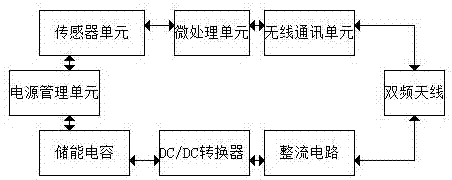
[0030] Such as figure 1 , a wireless sensor network capable of remote wireless charging in the present invention, comprising a sending end and a receiving end, the sending end includes a transmitting module; the receiving end includes a sensor node module and an energy collection module; the sensor node module includes a sensor unit , a micro-processing unit, a wireless communication unit; the micro-processing unit includes an A / D converter and an MCU, which connec...


PUM


Abstract

The invention discloses a wireless sensor network capable of remote wireless charging, which is characterized in that: it includes a sending end and a receiving end, the sending end includes a transmitting module; the receiving end includes a sensor node module and an energy collection module; the sensor The node module includes a sensor unit, a micro-processing unit, and a wireless communication unit; the micro-processing unit includes an A/D converter and an MCU, which connects the sensor unit and the wireless communication unit; the energy collection module includes an antenna and a rectifying circuit connected in sequence , a DC/DC converter, an energy storage capacitor and a power management unit; the power management unit is connected to a micro-processing module; the antenna is connected to a wireless communication unit and a rectifier circuit; the antenna is a dual-frequency antenna. The wireless sensor network of the invention realizes the function of remote wireless charging and solves the energy supply problem of the wireless sensor network.

Description

technical field [0001] The invention relates to the field of wireless sensor networks, in particular to a wireless sensor network capable of remote wireless charging. Background technique [0002] The wireless sensor network is composed of low-cost, dense, randomly distributed nodes. Its self-organization and fault tolerance make it impossible to cause the collapse of the entire system due to the damage of some nodes. The wireless connection makes its deployment almost unaffected by the monitoring objects. Impact maintenance costs are very low. Therefore, this network system can be widely used in national defense and military, environmental monitoring, medical and health care, smart home, manufacturing and other fields. [0003] Although the application prospect of wireless sensor network is very good, the power supply method has become a major problem restricting its development. Generally, batteries are used to supply power to various micro devices, but traditional batte...

Claims


Application Information

Patent Timeline
Patent Type & Authority Applications(China)
IPC IPC(8): H04W84/18H02J50/20
CPCH04W84/18H02J7/025
Inventor 王翔
Owner 王翔
Why Eureka
Try Eureka