
Power frequency follow current testing device and application method thereof

A test device and power frequency freewheeling technology, applied in measuring devices, overload protection devices, test circuits, etc., can solve the problems of low voltage and current levels, small output maximum power frequency short-circuit current amplitude, and difficulty in simulating arrester working conditions and other issues to achieve the effect of ensuring reliability and high reliability

Pending Publication Date: 2017-12-22
STATE GRID HUNAN ELECTRIC POWER +2
View PDF0 Cites 11 Cited by
  • Summary
  • Abstract
  • Description
  • Claims
  • Application Information

AI Technical Summary

Problems solved by technology

[0004] However, the impulse voltage generator system and power frequency test power supply system in the existing power frequency freewheeling test device often have shortcomings such as low output voltage and current levels, and small output maximum power frequency short-circuit current amplitude. Under the actual operating conditions, there are certain defects when evaluating the ability of the arrester gap to extinguish the power frequency arc

Method used


Image

  • Power frequency follow current testing device and application method thereof
  • Power frequency follow current testing device and application method thereof
  • Power frequency follow current testing device and application method thereof

Examples


Embodiment Construction

[0027] In order to make the objectives, technical solutions, and advantages of the embodiments of the present invention clearer, the technical solutions in the embodiments of the present invention will be clearly described below in conjunction with the accompanying drawings in the embodiments of the present invention. Obviously, the described embodiments are the present invention. Invented some embodiments, but not all embodiments. Based on the embodiments of the present invention, all other embodiments obtained by those of ordinary skill in the art without creative work shall fall within the protection scope of the present invention.

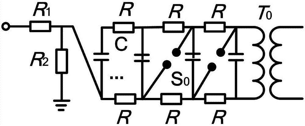
[0028] figure 1 It is a structural block diagram of a power frequency continuous current test device provided by an embodiment of the present invention, such as figure 1 As shown, the power frequency continuous current test device includes: an impulse power supply 101, a power frequency power supply 102, a product to be tested 103, a power frequenc...


PUM

PropertyMeasurementUnit
Capacitanceaaaaaaaaaa
Thicknessaaaaaaaaaa
Thicknessaaaaaaaaaa

Abstract

The invention provides a power frequency follow current testing device and an application method thereof; the testing device comprises the following units: a power transformer used for converting a power grid voltage into a power frequency voltage, wherein the power transformer winding inter-turn insulating material employs yellow varnished silk, and the inter-layer insulating material employs fiberglass cladding flat wire; an impact voltage generator with the charging capacitor electric capacity as 0.05 [mu]F, a wave front resistor resistance as 80 [omega] and a wave tail resistor resistance as 2100 [omega]; the impact voltage generator is connected in series with an impact side protection circuit, and then the output end is connected in parallel with a tested product; the power transformer and a power frequency side protection circuit are connected in parallel, and then the output end is connected in parallel with the tested product; the testing device also comprises a control measuring circuit used for determining whether to trigger to form an impact voltage or not according to the power frequency power phase. The testing device can better simulate the lightning wave conditions happening in network operations, can bear higher overvoltage and overcurrent, thus ensuring high reliability, and using fewer protection circuits.

Description

Technical field [0001] The invention relates to the technical field of electrical engineering, and more specifically, to a power frequency continuous current test device and a method of use thereof. Background technique [0002] Lightning strikes are widespread in power systems. According to statistics, 70% of power outages and trips in power systems are caused by lightning. Zinc oxide arresters are installed in the power system to divert the lightning current and suppress the amplitude of lightning overvoltage. With the continuous development of the power system, power users have put forward higher requirements for the reliability and stability of power equipment. Therefore, it is necessary to test the lightning arrester in the power system to evaluate its stability under the action of lightning overvoltage Sex and reliability. [0003] Existing power frequency continuous current test devices include: impulse voltage generator system for outputting impulse voltage, power frequen...

Claims


Application Information

Patent Timeline
IPC IPC(8): G01R31/14G01R31/00G01R1/28G01R1/36
CPCG01R1/28G01R1/36G01R31/003G01R31/1227
Inventor 陆佳政谢鹏康蒋正龙方针李波胡建平
Owner STATE GRID HUNAN ELECTRIC POWER
Learn More