
Automobile transmission shaft structure

A transmission shaft and automobile technology, which is applied in the field of automobile transmission, can solve the problems of high machining accuracy and heavy weight of the transmission shaft assembly, and achieve the effects of reducing weight, fixing firmly, and reducing residual unbalance

Inactive Publication Date: 2017-12-22
ANHUI JIANGHUAI AUTOMOBILE GRP CORP LTD
View PDF6 Cites 0 Cited by
  • Summary
  • Abstract
  • Description
  • Claims
  • Application Information

AI Technical Summary

Problems solved by technology

[0017] The purpose of the present invention is to provide an automobile transmission shaft structure to solve the problems of heavy weight, high processing precision requirements and the need for balance weights of different sizes in the prior art transmission shaft assembly

Method used


Image

  • Automobile transmission shaft structure
  • Automobile transmission shaft structure
  • Automobile transmission shaft structure

Examples


Embodiment Construction

[0058] The technical solution of the present invention is described in detail below through the examples, and the following examples are only exemplary and can only be used to explain and illustrate the technical solution of the present invention, rather than being interpreted as a limitation to the technical solution of the present invention.

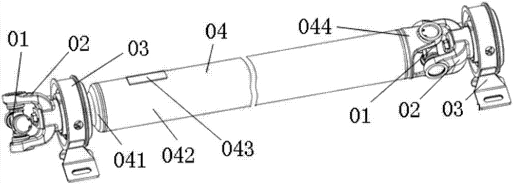
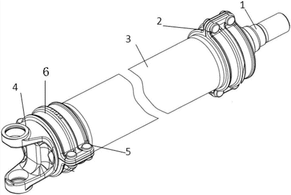
[0059] The application provides an automobile drive shaft structure, such as Figure 2 to Figure 12 As shown, it includes a shaft head, a housing, a shaft yoke, a first bearing bush and a second bearing bush.

[0060] One end of the shaft head is inserted into one end of the casing and fixedly connected through the first bearing bush; one end of the shaft fork is inserted into the other end of the casing and fixedly connected through the second bearing bush.

[0061] The shaft head is a rotating body, and along the axial center line of the shaft head, it sequentially includes a cross shaft bracket installation part, a bearing installat...


PUM


Abstract

The invention relates to an automobile transmission shaft structure. The automobile transmission shaft structure comprises a shaft head, a shell body, a shaft fork, a first bearing shell and a second bearing shell; one end of the shaft head is inserted into one end of the shell body and is fixedly connected through the first bearing shell; and one end of the shaft fork is inserted into the other end of the shell body and is fixedly connected through the second bearing shell. According to the automobile transmission shaft structure, the shell body is set as an FRP reinforced plastic, thus the weight of the transmission shaft is reduced, energy is saved and consumption is reduced, the remaining unbalance of the transmission shaft is reduced, and the transmission shaft is firmly fixed.

Description

technical field [0001] The invention belongs to the technical field of automobile transmission, in particular to an automobile transmission shaft structure. Background technique [0002] The transmission shaft assembly is composed of a universal joint and a transmission shaft, and sometimes an intermediate support is added. It is mainly used to transmit torque and rotary motion between two shafts whose relative positions are constantly changing during the working process. [0003] The design of drive shaft assembly shall meet the following basic requirements: [0004] 1) Ensure that the power can be reliably transmitted when the relative position of the two connected shafts changes within the expected range. [0005] 2) Ensure that the connected two shafts run at the same speed as possible. The additional load, vibration and noise due to the included angle of the universal joint should be within the allowable range. [0006] 3) The transmission efficiency is high, the se...

Claims


Application Information

Patent Timeline
Patent Type & Authority Applications(China)
IPC IPC(8): F16D3/26F16D3/84F16C33/04
CPCF16C33/04F16C2361/41F16D3/265F16D3/841F16D2300/26
Inventor 刘守银刘俊红郭磊
Owner ANHUI JIANGHUAI AUTOMOBILE GRP CORP LTD
Learn More