Eureka AIR delivers breakthrough ideas for toughest innovation challenges, trusted by R&D personnel around the world.

Normally-open proportional one-way flow valve

A flow valve, one-way technology, applied in valve details, control valves, valve devices, etc., can solve the problems of rising cost of use and larger volume of hydraulic valve groups.

Active Publication Date: 2017-12-22
杭州富阳中亚阀业有限公司
View PDF7 Cites 2 Cited by
  • Summary
  • Abstract
  • Description
  • Claims
  • Application Information

AI Technical Summary

Problems solved by technology

The additional pressure compensator will inevitably lead to an increase in the cost of use and an increase in the volume of the hydraulic valve group, which is unacceptable to many customers; therefore, its structure needs to be further improved

Method used


Image

  • Normally-open proportional one-way flow valve
  • Normally-open proportional one-way flow valve
  • Normally-open proportional one-way flow valve

Examples


Embodiment Construction

[0020] The present invention will be further described in detail below in conjunction with the accompanying drawings and embodiments.

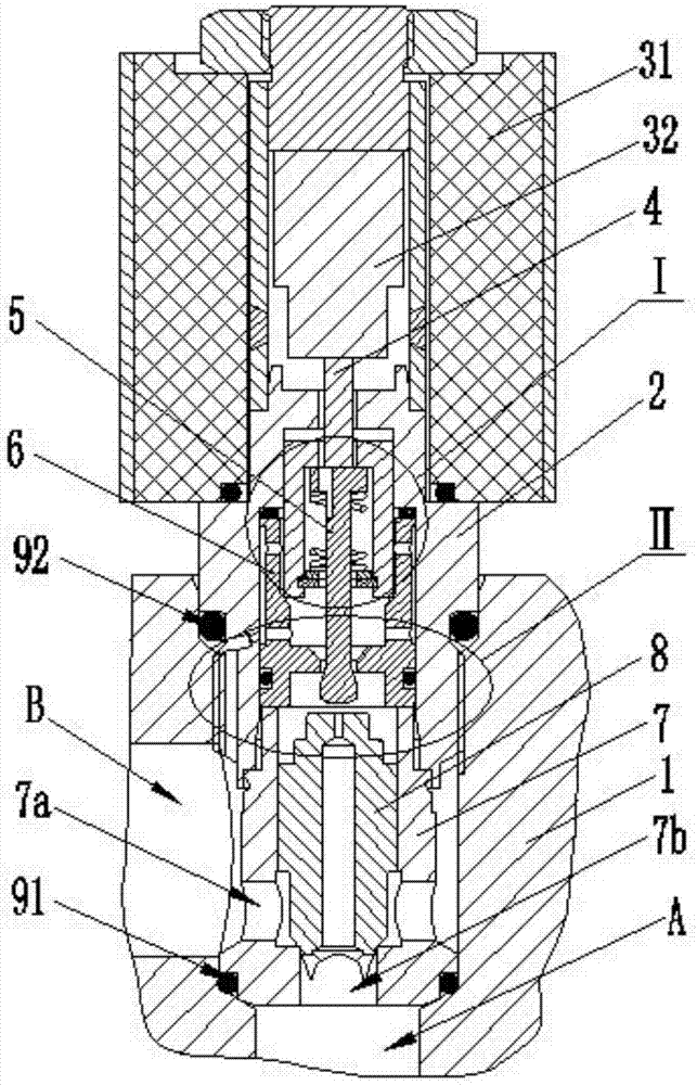
[0021] Such as Figure 1 to Figure 4 Shown is the structural representation of the present invention,

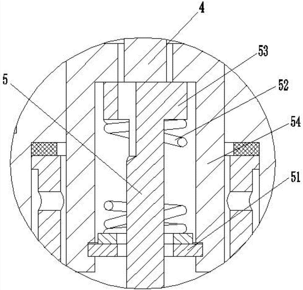
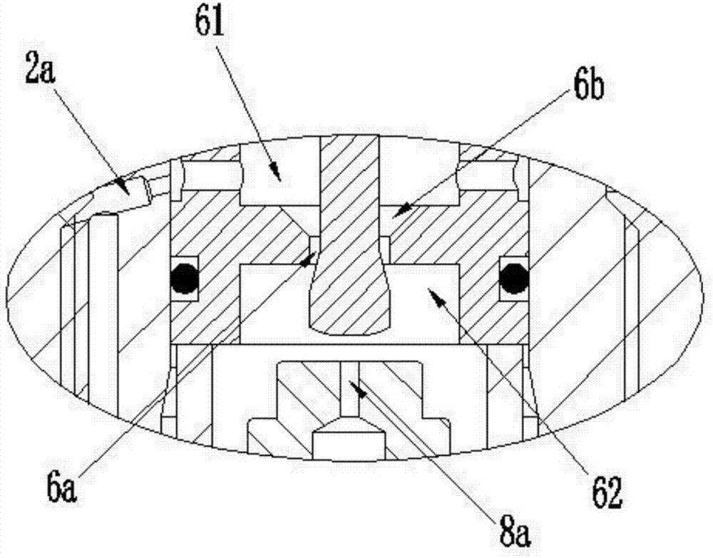
[0022] The reference signs are: A port, B port, valve body 1, screw sleeve 2, first damping hole 2a, proportional electromagnet 31, armature 32, ejector rod 4, pilot spool 5, stop ring 51, spring 52 , convex ring 53, spacer sleeve 54, positioning sleeve 6, throttle hole 6a, taper hole 6b, pressure feedback chamber 61, hydraulic control chamber 62, valve sleeve 7, side oil hole 7a, lower oil hole 7b, main valve core 8 , the second damping hole 8a, the first sealing ring 91, and the second sealing ring 92.

[0023] Such as Figure 1 to Figure 3 as shown,

[0024] A normally open proportional one-way flow valve, including a valve body 1, which is provided with A port and B port, the upper part of the valve body 1 is screwed with a screw sle...


PUM


Abstract

The invention discloses a normally-open proportional one-way flow valve. The normally-open proportional one-way flow valve comprises a valve body provided with a port A and a port B. The upper portion of the valve body is in screw joint with a screw sleeve. A proportional electromagnet is assembled to the upper portion of the screw sleeve. An armature is arranged at the center of the proportional electromagnet. The lower end of the armature abuts against and is matched with a piloted valve element in the screw sleeve through an ejector rod. A spring is arranged between the upper portion of the piloted valve element and a stop ring. The lower end of the piloted valve element penetrates a throttling hole in the center of a positioning sleeve. A pressure feedback cavity is formed above the throttling hole. A hydraulic control cavity is formed below the throttling hole. A valve sleeve is arranged in the part, below the positioning sleeve, in the valve body. A main valve element is arranged at the center of the valve sleeve. The valve sleeve is provided with a side oil hole communicating with the port B and a lower oil hole communicating with the port A. A first damping hole is formed in the side wall of the screw sleeve and communicates with the port B. A second damping hole is formed in the center of the main valve element and communicates with the lower oil hole. The aperture of the upper throttling hole of the positioning sleeve is changed through the up-down movement of the piloted valve element, and the beneficial effect that flow stability is kept when loads change is achieved.

Description

technical field [0001] The invention relates to the technical field of electromagnetic valve manufacturing, in particular to a normally open proportional one-way flow valve. Background technique [0002] In recent years, proportional one-way flow valves have been used more and more in lifting equipment such as truck-mounted cranes, aerial work vehicles, tractor rotary plows, and electric forklifts. When the equipment stops, the proportional one-way flow valve plays the role of maintaining pressure to prevent the hydraulic cylinder from sliding down; when the equipment needs to descend, the proportional one-way flow valve controls the size of the opening according to the input voltage signal and adjusts the output flow of the hydraulic cylinder , and then control the descending speed of the lifting equipment. [0003] For example, the patent No. 201510807564.0 titled "a high-horsepower tractor lifter valve group" discloses a hydraulic valve group for controlling the tractor ...

Claims


Application Information

Patent Timeline
IPC IPC(8): F15B13/02F16K31/06F16K31/36F16K15/02
CPCF15B13/027F16K15/02F16K31/0644F16K31/36
Inventor 陈艳艳
Owner 杭州富阳中亚阀业有限公司
Why Eureka
Eureka Blog
Learn More