
Novel binding tape cutting machine

A cutting and baling machine, a new type of technology, applied in metal processing, grinding/polishing hand tools, metal processing equipment, etc. The effect of preventing safety hazards and preventing tool damage

Pending Publication Date: 2017-12-22
JIANGSU YUEDA HOME TEXTILE
View PDF5 Cites 4 Cited by
  • Summary
  • Abstract
  • Description
  • Claims
  • Application Information

AI Technical Summary

Problems solved by technology

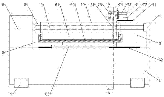
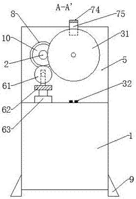
[0003] At present, the existing defects of the existing strip cutting machine are: 1) When the moving cutting mechanism cuts the raw material core on the rotating mandrel, the raw material core is continuously cut, and the stability of the overall rotation is not good , it is easy to cause uneven size of the bundle after cutting, which affects the quality of the bundle; 2) The round knife of the mobile cutting mechanism is easy to passivate after long-term use, and it is necessary to manually grind the two edge surfaces of the round knife with a whetstone. On the one hand, there will be potential safety hazards, and it is easy to cause personal injury when sharpening the knife. On the other hand, it is difficult to grasp the accuracy of knife sharpening, which may easily cause damage to the knife, thus affecting product quality.

Method used


Image

  • Novel binding tape cutting machine
  • Novel binding tape cutting machine

Examples


Embodiment Construction

[0015] The present invention will be further clarified below in conjunction with the drawings and specific embodiments. It should be understood that the following specific embodiments are only used to illustrate the present invention and not to limit the scope of the present invention. It should be noted that the words "front", "rear", "left", "right", "upper" and "lower" used in the following description refer to the directions in the drawings, and the words "inner" and "outer" "Respectively refers to the direction toward or away from the geometric center of a particular component.

[0016] As shown in the figure, a new type of cutting machine includes a worktable 1, a rotating mandrel 2 and a mobile cutting mechanism 3. The rotating mandrel 2 and the mobile cutting mechanism 3 are arranged on the worktable 1, and one end of the rotating mandrel 2 There is a bracket 4, the other end is matched with a drive motor 5, the mobile cutting mechanism 3 is arranged on one side of the ro...


PUM


Abstract

The invention provides a novel binding tape cutting machine. The novel binding tape cutting machine comprises a working table, a rotating core shaft and a moving cutting mechanism. The working table is further provided with an abutting device and a cutter grinding device. The abutting device is arranged below the rotating core shaft and comprises an abutting rotating roller, a supporting base and a first lifting air cylinder. The cutter grinding device comprises a sliding guiding rail. The sliding guiding rail is arranged on the top of the moving cutting mechanism. The sliding guiding rail is provided with a second lifting air cylinder which can slide along the sliding guiding rail. A piston rod of the second lifting air cylinder is connected with a supporting plate. One end of the supporting plate is connected with the piston rod of the second lifting air cylinder. The other end of the supporting plate is connected with a cutter grinding shell. The novel binding tape cutting machine has the advantages that the abutting rotating roller can be tightly attached to the surface of the rotating core shaft, assisting and stabilizing functions are achieved, so that it is ensured that a cut binding tape is tidy is size, and the quality of the binding tape is improved; and by using the cutter grinding device, passivation of a round cutter is prevented, manually-held cutter grinding stone is not needed to grind the cutter, the potential safety hazard during cutter grinding is prevented, it is also ensured that the two edge surfaces of the round cutter are accurately ground, and damaging of the cutter is prevented.

Description

Technical field [0001] The invention relates to the technical field of light industrial equipment, in particular to a new type of cutting machine. Background technique [0002] The cutting machine is used for shoemaking, clothing, luggage, shoes and hats, clothing accessories, medical supplies, reflective material factories, tent factories, umbrella factories, gift packaging, bunting, decoration accessories and other industries. A must-have choice for bars. [0003] At present, the existing defects of the existing cutting machine are as follows: 1) When the mobile cutting mechanism cuts the raw material core on the rotating mandrel, the raw material core is continuously cut, and its overall rotation stability is not good. , It is easy to cause the size of the bundle after cutting to be uneven, which affects the quality of the bundle; 2) The round knife of the mobile cutting mechanism is easy to passivation after long-term use. Which sharpening stone is required to grind the two ed...

Claims


Application Information

Patent Timeline
Patent Type & Authority Applications(China)
IPC IPC(8): B26D1/157B26D7/01B26D7/12B24D15/08
CPCB24D15/084B26D1/157B26D7/01B26D7/12B26D2007/013
Inventor 凌良仲孙仁斌王娟娟李杨于灿
Owner JIANGSU YUEDA HOME TEXTILE
Learn More