
Positioning and fixing device for automobile part stamping die

A technology of stamping dies and fixing devices, which is applied in the field of positioning and fixing devices for stamping dies of auto parts, and can solve problems such as product displacement, troublesome operation, and low production efficiency

Inactive Publication Date: 2017-12-22
温州天和汽车部件有限公司
View PDF6 Cites 16 Cited by
  • Summary
  • Abstract
  • Description
  • Claims
  • Application Information

AI Technical Summary

Problems solved by technology

[0007] In order to overcome the shortcomings of the existing technical solutions, the present invention provides a positioning and fixing device for stamping dies of auto parts, which not only solves the problem that when the traditional positioning and fixing devices of stamping dies of auto parts are positioning auto parts, when the fixed body is fixed on the object On the surface, the surface of the part is often worn due to excessive pressure. It also solves the problem that the positioning and fixing device of the traditional auto parts stamping die often causes the product to be fixed when the part is not uniformly stressed. Displacement occurs, which leads to the problem of shifting the fixed position, and also solves the problem that when the positioning and fixing device of the existing stamping die for auto parts is used, human power is often required to adjust the pressure, which leads to troublesome operation and low production efficiency.

Method used

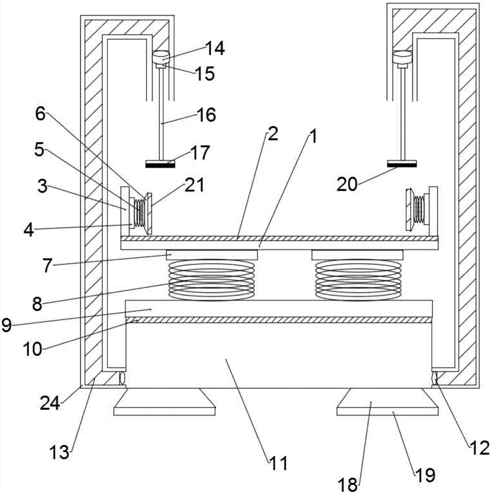
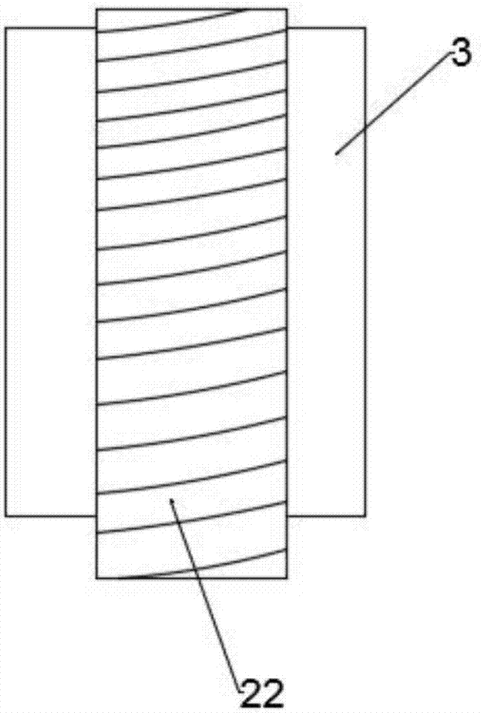
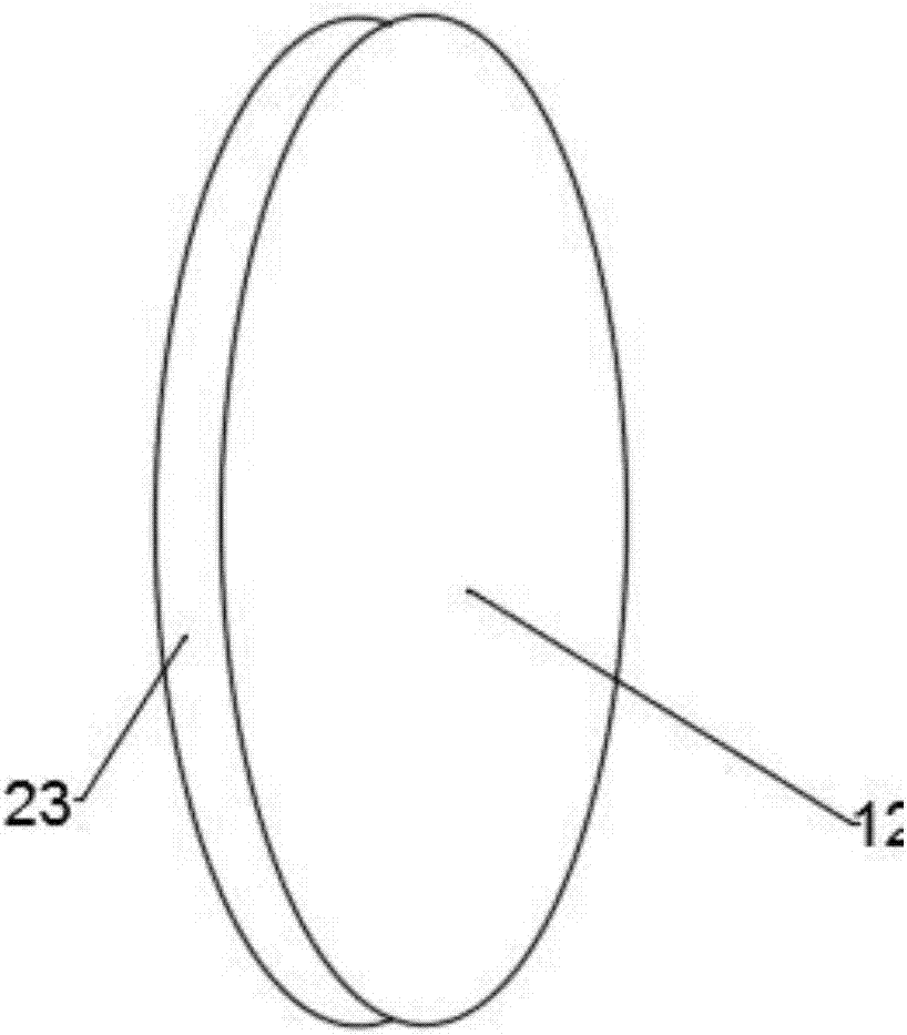

Image

  • Positioning and fixing device for automobile part stamping die
  • Positioning and fixing device for automobile part stamping die
  • Positioning and fixing device for automobile part stamping die

Examples


Embodiment

[0027] Such as figure 1 As shown, the present invention discloses a positioning and fixing device for stamping dies of automobile parts, which is characterized in that it includes a base 1 and a fixing rod 16, a bottom fixing block 2 is arranged above the base 1, and the bottom fixing block 2 A bottom spring 3 is arranged above, and the top of the bottom spring 3 is arranged on the bottom support block 4, and a lower support plate 5 is arranged above the bottom support block 4, and a pressure plate fixing block 6 is arranged on the left side of the lower support plate 5, so that A strut 7 is arranged above the pressing plate fixing block 6, a pressing plate 8 is disposed above the strut 7, a bottom convex body 9 is disposed above the lower supporting plate 5, and a rotating machine 10 is disposed at the right end of the supporting plate 5, so that The left end of the rotating machine 10 is provided with an outer telescopic rod 11, the outer telescopic rod 11 is provided with a...


PUM


Abstract

The invention discloses a positioning and fixing device for an automobile part stamping die. The positioning and fixing device comprises a plate surface, a movable groove is formed in the upper surface of the plate surface, and baffle plates are arranged at the two ends of the plate surface; a fixed body is arranged on the right side of each baffle plate, a spring is arranged on the right side of each fixed body, and a top body is arranged on the right side of each spring; fixed ends are arranged on the lower part of the plate surface, elastic support bodies are arranged on the lower parts of the fixed ends, a compression plate is arranged on the lower parts of the elastic support bodies, and an air bag cavity is formed in the lower part of the compression plate; piston floating bodies are arranged at the lower end openings of hydraulic cabins, and upper floating bodies are arranged at the upper end openings of the hydraulic cabins; connecting blocks are arranged on the lower end surfaces of the floating bodies, connecting rods are arranged at the lower ends of the connecting blocks, and pressing bodies are arranged at the bottom ends of the connecting rods; fixing feet are arranged at the bottom end of the air bag cavity; and protective shells are arranged on the outer sides of the surfaces of the hydraulic cabins. The positioning and fixing device solves the problems that the surface of a part is worn due to the traditional device and a fixed position is offset due to the traditional device, and further solves the problem that the pressure of the existing device needs to be adjusted by human power.

Description

technical field [0001] The invention relates to the technical field of positioning and fixing, in particular to a positioning and fixing device for stamping dies of automobile parts. Background technique [0002] For the assembly of various parts of automobiles, it is necessary to ensure high stability and precision of the parts during stamping. To avoid the lateral force causing the upper die to be unstable during the pressing process, which will affect the processing accuracy and life of the parts, it is necessary to The structure of the stamping die is optimized to achieve the minimum lateral force and improve the stability of the movement of the upper die. [0003] The application number is 201620959110.5, which is an invention patent for a positioning and fixing device for stamping dies of automobile parts. It can be firmly fixed by a punching machine. In order to improve the stretching effect of auto parts, a stretching die is set between the die base and the upper di...

Claims


Application Information

Patent Timeline
IPC IPC(8): B21D37/10B21D43/00B21D53/88
CPCB21D37/10B21D43/003B21D53/88
Inventor 孙中乐王立民
Owner 温州天和汽车部件有限公司
Learn More