Inspection apparatus

A technology of inspection device and mobile device, which is applied to measurement devices, transportation and packaging, and exploration of nuclear radiation, etc., can solve the problems of baffle structure, complicated control, large baffle size, and speed reduction, and shorten the inspection time. , The effect of preventing radiation leakage

Active Publication Date: 2017-12-19
ORMON CORPORATION
View PDF5 Cites 5 Cited by
  • Summary
  • Abstract
  • Description
  • Claims
  • Application Information

AI Technical Summary

Problems solved by technology

[0009] However, as in the inspection device described in Patent Document 3, when a plurality of shielding baffles are provided, the structure and control of the baffles become complicated and the cost of the device increases.
In addition, when the invention described in Patent Document 3 is applied to a double track structure, there is a problem that the size of the baffle is increased, resulting in a decrease in speed.

Method used


Image

  • Inspection apparatus
  • Inspection apparatus
  • Inspection apparatus

Examples


no. 1 approach

[0063]

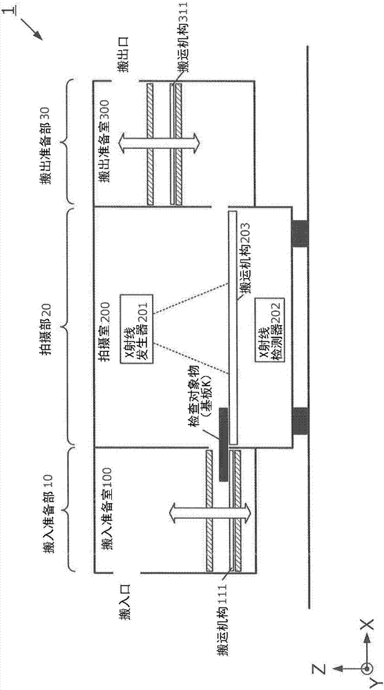
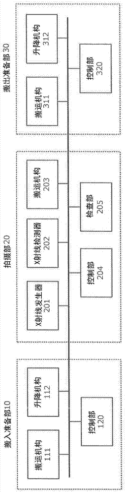
[0064] First, refer to figure 1 and figure 2 , the configuration of the X-ray inspection apparatus according to this embodiment will be described. figure 1 is a cross-sectional view schematically showing the X-ray inspection apparatus 1 of the present embodiment, figure 2 It is a block diagram showing the configuration and functions of the X-ray inspection apparatus 1 . Such as figure 1 and figure 2 As shown, the X-ray inspection apparatus 1 has a carry-in preparation unit 10 , an imaging unit 20 , and a carry-out preparation unit 30 .

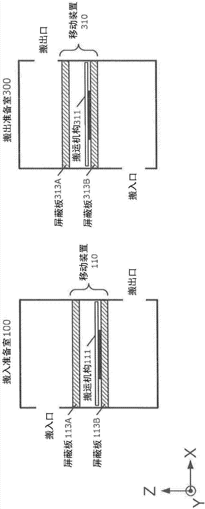
[0065] in addition, figure 1 is a diagram schematically showing the flow of the substrate during the inspection, refer to the following image 3 A device for shielding X-rays will be described.

[0066] Such as figure 1 As shown, the main body of the X-ray inspection apparatus 1 is provided with an imaging unit 20 for performing X-ray imaging, and a loading preparation unit for loading the substrate K of the inspection ob...

no. 2 approach

[0122] In the first embodiment, the conveyance mechanism 203 is fully covered in the imaging chamber 200, and the substrate placed on the conveyance mechanism 203 moves. In contrast, the second embodiment is an embodiment in which the substrate is moved by the moving transport mechanism 203 itself. Figure 8 It is a sectional view schematically showing the X-ray inspection apparatus 1 of the second embodiment.

[0123] As shown in the figure, in this embodiment, the transport mechanism 203 can move along the X-axis direction in the figure.

[0124] In the second embodiment, the transport mechanism 203 is moved to a position capable of receiving the substrate before the process of step S21 is started. In addition, before the process of step S25 is started, the transport mechanism 203 is moved to a position where the substrate can be discharged. In addition, after step S27 ends, while the conveyance mechanism 203 is moved to the position which can receive a board|substrate, th...


PUM


Abstract

The present invention provides an inspection apparatus using radiation, which prevents radiation leakage and shortens the inspection time. An inspection apparatus includes a feed-in preparation chamber, an imaging chamber, and a feed-out preparation chamber. Each preparation chamber includes a feed-in unit that receives an inspection object through a first opening, a traverser that translates the received object to a second opening in a direction different from the receiving direction of the object, and a feed-out unit that moves the object in a direction different from a moving direction of the traverser and discharges the object through the second opening. The imaging chamber includes an imaging unit that images the object fed from the feed-in preparation chamber. The traverser includes a mount for the object, and a shield that moves together with the mount and prevents radioactive rays entering one of the first and second openings and propagating in the moving direction of the traverser from reaching the other opening.

Description

technical field [0001] The present invention relates to an inspection device using radiation. Background technique [0002] There is known a technique of non-destructively inspecting an inspection object using image information obtained by X-ray imaging. For example, Patent Document 1 discloses a method of reconstructing 3D data of board-mounted components by X-ray CT (computer tomography: computer tomography), and inspecting the quality of soldering based on the 3D data. This type of X-ray inspection device can perform high-precision inspection of the internal structure and fine structure of the inspection object, so it has begun to be used in automatic inspection of various industrial product production lines. [0003] Inspection devices used on an inline (Inline) are required to shorten the inspection cycle time as much as possible in order to prevent stagnation in the inspection process. Therefore, as shown in Patent Document 2, the following structure is known: two co...

Claims


Application Information

Patent Timeline
IPC IPC(8): G01N23/04
CPCG01N23/04G01N2223/3308G01V5/22B65G15/00G01N23/046G01N2223/3307G01N2223/419G01N2223/643G01N2223/646G21K1/04
Inventor 杉田信治大西贵子太田佳秀
Owner ORMON CORPORATION
Why Eureka
Try Eureka