An emergency brake release valve and its valve core locking method
A technology of emergency braking and air release valve, applied in the direction of lift valve, valve details, valve device, etc., can solve the problems of low exhaust efficiency, affecting the braking effect of emergency air release valve, unstable valve core position, etc., to achieve tightness Good, fast and effective ventilation, simple structure effect
- Summary
- Abstract
- Description
- Claims
- Application Information
AI Technical Summary
Problems solved by technology
Method used
Image
Examples
Embodiment 1
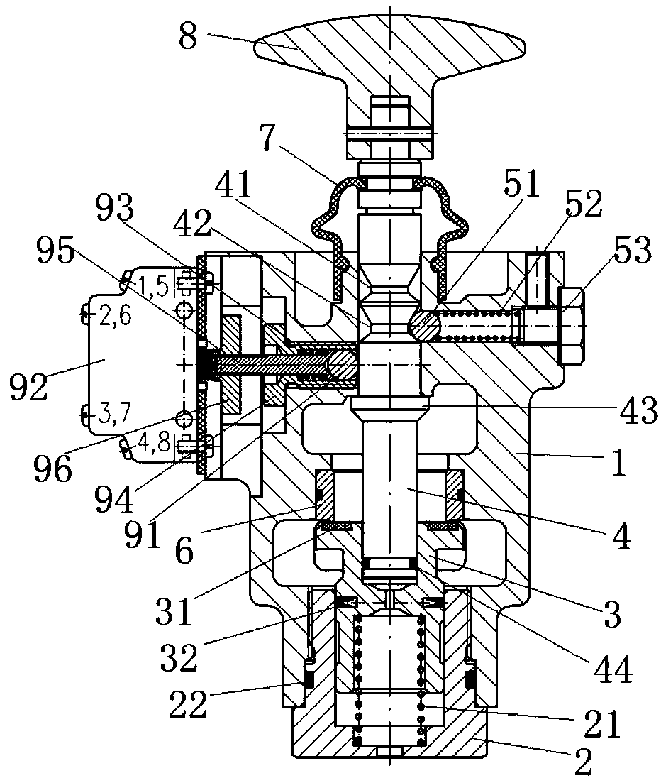
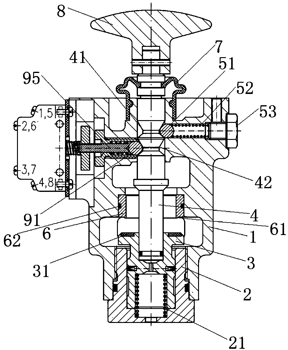
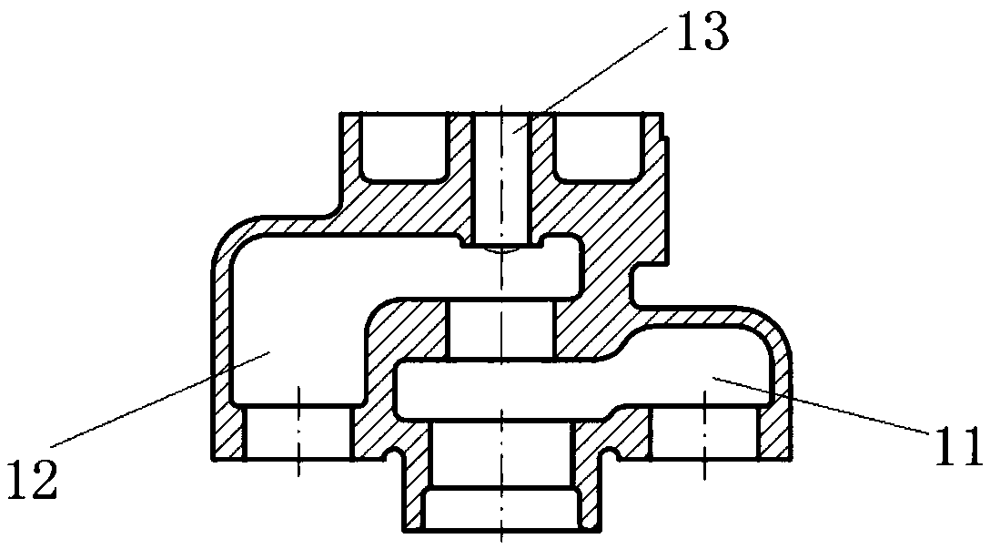
[0030] See Figure 1 to Figure 3 As shown, it is a cross-sectional view of the emergency brake vent valve in a closed state, a cross-sectional view in an open state, and a cross-sectional view of the valve body of the present invention.
[0031] Combine figure 1 with image 3 As shown, an emergency brake vent valve includes a valve body 1, a valve cover 2, a valve core 3, a push rod 4, and a locking mechanism. The valve body 1 is provided with an air inlet chamber 11 and a vent chamber 12, so A valve port 6 is provided between the air inlet chamber 11 and the air discharge chamber 12, the valve cover 2 is detachably connected with the valve body 1, and a thrust spring is provided between the valve cover 2 and the bottom of the valve core 3 21. The top of the valve core 3 bears against the valve port 6, so that the air release valve is in a normally closed state, one end of the push rod 4 penetrates into the valve body 1 and is in contact with the top of the valve core 3, and the p...
Embodiment 2
[0037] An emergency brake vent valve as described above, this embodiment differs from it in that, figure 1 As shown, the locking mechanism includes a steel ball A 51, an elastic element, and an adjustment member for adjusting the amount of expansion and contraction of the elastic element. The steel ball A51 is supported by the elastic element and falls into one of the limiting grooves. It is used to fix the position of the push rod 4 to lock the valve core.
[0038] Among them, in this embodiment, such as figure 1 As shown, the elastic element is preferably a positioning spring 52, and the adjusting member is preferably an adjusting bolt 53; adjusting the adjusting bolt 53 can adjust the tension of the positioning spring 52, thereby adjusting the steel ball A 51 and the limit groove Locking force. When the air release valve is in the closed state, the steel ball A 51 falls into the lower locking groove 42, and the stress point of the push rod 4 is the upper trapezoidal edge of th...
Embodiment 3
[0040] An emergency brake vent valve as described above, this embodiment differs from it in that: Picture 11 with Picture 12 As shown, the limiting groove is a trapezoidal groove, that is, the upper locking groove 41 and the lower locking groove 42 are both trapezoidal grooves, and the angles between the upper and lower trapezoidal sides and the bottom side are obtuse angles. The angle between the trapezoid side and the bottom side is 90°+α 1 , The angle between the lower trapezoidal side and the bottom side is 90°+α 2 . The α 1 The range of is 20°~60°, which is to reduce the force of pushing the push rod 4 and prevent the valve core 3 from being locked, causing the air release valve to fail to realize the function of emergency air release; the α 2 The range of is 0°~45°, which is beneficial for the air release valve to prevent the valve core 3 from rebounding in the case of emergency braking.
[0041] The force F 1 Decomposed into vertical force F Rod And the horizontal force ...
PUM
 Abstract
Description
Claims
Application Information
 - R&D
- Intellectual Property
- Life Sciences
- Materials
- Tech Scout
- Unparalleled Data Quality
- Higher Quality Content
- 60% Fewer Hallucinations
Browse by: Latest US Patents, China's latest patents, Technical Efficacy Thesaurus, Application Domain, Technology Topic, Popular Technical Reports.
© 2025 PatSnap. All rights reserved.Legal|Privacy policy|Modern Slavery Act Transparency Statement|Sitemap|About US| Contact US: help@patsnap.com


