
Sludge treatment equipment

A sludge treatment and equipment technology, applied in the direction of dewatering/drying/concentrating sludge treatment, etc., can solve the problem of water yield less than 50%, and achieve the effect of less residue, fast discharge and better filtration effect

Active Publication Date: 2017-12-19
天津颐和中威精密机器有限公司
View PDF2 Cites 6 Cited by
  • Summary
  • Abstract
  • Description
  • Claims
  • Application Information

AI Technical Summary

Problems solved by technology

However, when the sludge is squeezed, the sludge is often squeezed into a mud cake, and the moisture in the sludge in the mud cake is difficult to separate, so the water yield can not reach 50%.

Method used


Image

  • Sludge treatment equipment
  • Sludge treatment equipment
  • Sludge treatment equipment

Examples


Embodiment

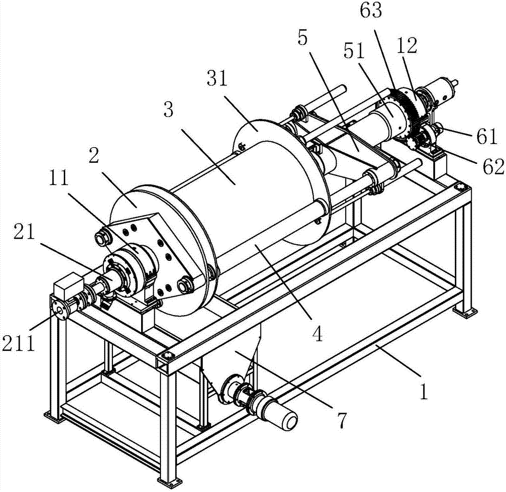
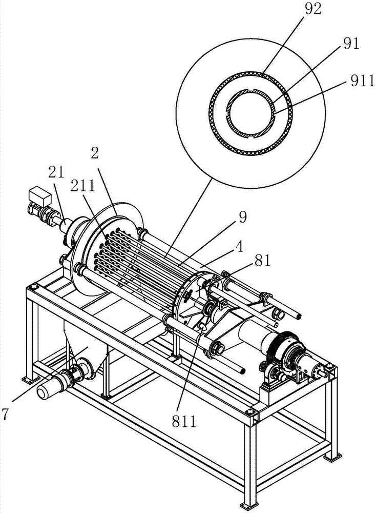
[0032] Embodiment: a kind of sludge treatment equipment, such as figure 1 and figure 2 As shown, it includes a frame 1, an end cover 2, a feeding device and a driving device.

[0033] The discharging device includes a base 5, a cylinder body 3, a slide rail 4 and a piston mechanism. The two ends of the frame 1 are respectively provided with a bearing seat 11 and a bearing seat 2 12, and one end of the end cover 2 is provided with a feeding cylinder 21. The feed cylinder 21 is horizontally rotatably supported on the first bearing seat 11 , and the feed cylinder 21 is provided with a feed port 211 communicating with the other end surface of the end cover 2 . One end of the base 5 is provided with a support tube 51 , and the support tube 51 is horizontally rotatably supported on the bearing seat 2 12 . One end of the slide rail 4 is fixedly connected to the end cover 2, and the other end is fixedly connected to the base 5. The two ends of the cylinder body 3 protrude outward t...


PUM


Abstract

The invention discloses sludge treatment equipment. According to the key point of the technical scheme, the sludge treatment equipment comprises a machine frame, an end cover, a discharging device and a driving device, wherein the end cover is supported on the machine frame in a horizontal rotating manner; the discharging device is supported on the machine frame in the horizontal rotating manner; the driving device drives the discharging device to rotate; the discharging device comprises a base, a barrel, a sliding rail, a power mechanism and a piston mechanism; the base is rotatably supported on the machine frame; the barrel is in connection in a horizontal sliding manner relative to the base and is in butt joint with the end cover; the sliding rail is used for the barrel to perform sliding connection and is fixedly connected with the end cover; the power mechanism drives the barrel to slide horizontally; the piston mechanism is arranged at the other end, opposite to the end cover, of the barrel; a plurality of flexible filter tubes are connected between the end cover and the piston mechanism; a feeding port is formed in the end cover; and a liquid outlet is formed in the end parts of the filter tube. The sludge treatment equipment solves the problem that the water outlet rate is not high when the conventional sludge treatment equipment performs solid and liquid separation.

Description

technical field [0001] The invention relates to the field of sludge treatment, more specifically, it relates to a sludge treatment equipment. Background technique [0002] Domestic and industrial sludge contains a large amount of water resources, which will cause great waste if not treated. For this reason, some sludge treatment equipment has emerged as the times require to treat the water in the sludge and turn waste into treasure, which not only saves water resources, but also protects the environment. [0003] Among them, the filter press is a common sludge treatment equipment. The filter press is a commonly used solid-liquid separation equipment. It uses a pressure system to exert a certain pressure on the object to make the liquid dialysis out. It was used in the early 18th century. It is used in chemical production and is still widely used in chemical, pharmaceutical, metallurgy, dye, food, brewing, ceramics and environmental protection industries. Existing filter pr...

Claims


Application Information

Patent Timeline
Patent Type & Authority Applications(China)
IPC IPC(8): C02F11/12
Inventor 王秀川
Owner 天津颐和中威精密机器有限公司
Learn More