
High-efficient dust removal device

A dust-removing device and high-efficiency technology, which can be used in dry gas layout, photovoltaic modules, filter circuits, etc., can solve the problem that the cleaning mechanism does not have the function of water spray, and achieve the advantages of enhancing the comprehensive mechanical properties of machinery, saving water resources, and improving cleaning efficiency. Effect

Inactive Publication Date: 2017-12-19
浦江县顺光科技有限公司
View PDF4 Cites 7 Cited by
  • Summary
  • Abstract
  • Description
  • Claims
  • Application Information

AI Technical Summary

Problems solved by technology

The cleaning mechanism in the existing cleaning equipment does not have the function of spraying water

Method used


Image

  • High-efficient dust removal device
  • High-efficient dust removal device
  • High-efficient dust removal device

Examples


Embodiment 1

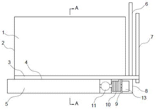
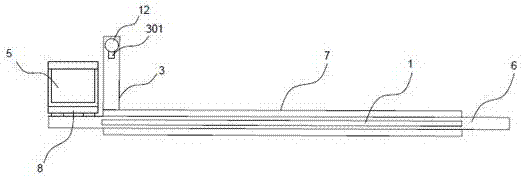
[0019] like Figure 1~3 As shown, a high-efficiency dust removal device includes a photovoltaic panel 1, a nozzle bracket 3 connected to the photovoltaic panel 1 by the first edge 4, a water pipe 12 is arranged on the nozzle bracket, and evenly distributed nozzles 301 are arranged below the water pipe 12. The nozzle bracket 3. There is a water collection tank 5 connected to the rear. The water collection tank 5 includes a tank body and a cover. The cover body is pivotally connected to the tank body, and the cover body is also connected to the second motor. 5 One end is connected to a water pump 11, the water pump 11 is connected to the rotating shaft 9 through the hose 10, the rotating shaft 9 is connected to the first motor 13, the sump 5 and the water pump 11 are respectively connected to the bracket 8, and the photovoltaic panel 1 is on the side of the second edge 2 A first slide rail 7 is provided, and the first slide rail 7 is slidingly connected with the nozzle bracket 3...

Embodiment 2

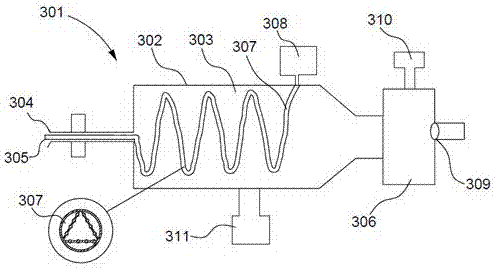
[0023] like Figure 1-3 As shown, a simple photovoltaic panel cleaning device of the present invention is suitable for installation on the photovoltaic panel 1 under strong sunlight. On the tank body, rainwater can be retained for as long as possible. In sunny or cloudy days, the cover body is closed on the tank body. In rainy or snowy days, the cover body is opened, and the tank body collects rainwater. When it is necessary to clean the photovoltaic panel 1 At this time, the water pump 11 can draw water from the water collection tank 5, and deliver it to the water pipe 12 on the nozzle bracket 3 through the hose 10, and then spray it out from the nozzle 301. When the nozzle 301 is in use, the water inlet is connected to the water supply pipe, and the water flows out The water outlet is sprayed out, and the water outlet and the cavity 303 are integrated. In order to adjust the direction of water spray, an adjustment bracket 311 is provided under the housing 302 to adjust the w...


PUM


Abstract

The invention discloses a high-efficient dust removal device. The dust removal device comprises a photovoltaic panel; a spray head support is connected with a first edge of the photovoltaic panel, a water pipe is arranged on the spray head support, and uniformly-distributed spray heads are arranged on the lower part of the water pipe; a water collecting groove is connected behind the spray head support, one end of the water collecting groove is connected with a water pump, the water pump is connected with a rotating shaft through a hose, and the rotating shaft is connected with a first motor; the water collecting groove and the water pump are connected with a support; a first slide rail is arranged beside the side part of a second edge of the photovoltaic panel, and the first slide rail is in sliding connection with the spray head support; and the spray head support is further connected with an air cylinder. According to the dust removal device, the photovoltaic panel can be washed and dried, and most of cleaning water adopts rainwater stored in rainy days so that resources can be saved; and rust-proof coatings coat the positions of the spray head and the spray head support so that corrosion affects cleaning effect can be effectively avoided, and therefore the service life of cleaning equipment can be prolonged.

Description

technical field [0001] The invention belongs to the technical field of cleaning equipment, and in particular relates to a high-efficiency dust removal device. Background technique [0002] A photovoltaic panel module is a power generation device that generates direct current electricity when exposed to sunlight. It consists of thin, solid photovoltaic cells almost entirely made of semiconductor materials such as silicon. Since there are no moving parts, it can be operated for a long time without any wear and tear. Simple photovoltaic cells power watches and computers, and more complex photovoltaic systems light homes and power the grid. Photovoltaic panel assemblies can be made in different shapes, and the modules can be connected to generate more electricity. Photovoltaic panels are used on roofs and building surfaces, and even as part of windows, skylights or shading devices. These photovoltaic facilities are usually called building-attached photovoltaic systems. [000...

Claims


Application Information

Patent Timeline
Patent Type & Authority Applications(China)
IPC IPC(8): B08B3/02B08B3/14F26B21/00B01D36/04H02S40/10C09D163/00C09D5/10C09D7/12
CPCB01D36/04B08B3/02B08B3/14C08K2003/0893C08K2003/2275C08K2003/2296C08L2205/035C09D5/106C09D163/00F26B21/00H02S40/10C08L61/22C08L71/02C08K13/02C08K3/08C08K3/22Y02E10/50
Inventor 胡光琼
Owner 浦江县顺光科技有限公司
Learn More