A method and device for monitoring the tilting mechanism of an injection mold
A lifter mechanism, injection mold technology, applied in the direction of measuring device, machine/structural component testing, mechanical component testing, etc., can solve the problems of sudden breakage and jamming of the lifter mechanism of the injection mold, and is easy to adjust and handle. , Real-time display, the effect of reducing damage
- Summary
- Abstract
- Description
- Claims
- Application Information
AI Technical Summary
Problems solved by technology
Method used
Image
Examples
Embodiment 1
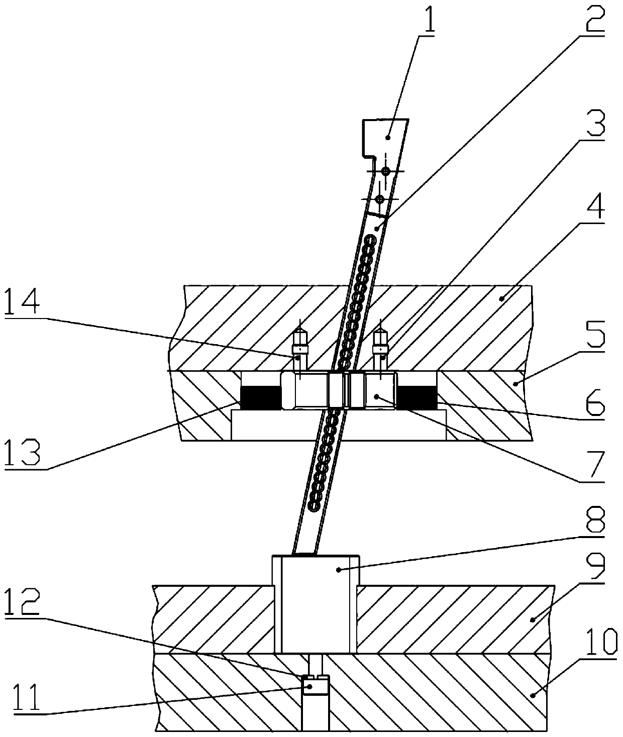
[0039] Embodiment 1, a method and device for monitoring a force sensor used for monitoring a tilting mechanism of an injection mold. The selected force sensor is a wireless strain sensor.
[0040] The monitoring device used in this embodiment includes: 1) a force sensor, 2) a wire, 3) a PC terminal, and 4) a wireless communication signal test analyzer.
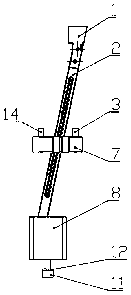
[0041] Such as figure 1 The wireless strain gauge force sensors 6 and 13 are respectively arranged between the support plate 5 and the guide block 7 to measure the force exerted by the jack rod 2 on the guide block 7 .
[0042] Wherein the guide block 7 is fixed on the movable formwork 4 by the hexagon socket head cap screw 3 and the hexagon socket head cap screw 14, at this time, the force bearing mode of the guide block 7 is that of a cantilever beam.
[0043] In the figure, the wireless strain gauge force sensors 6 and 13 are connected with the wireless communication signal test analyzer through wires.
[0044] The wirel...
Embodiment 2
[0051] Embodiment 2, a monitoring method and device of an optical fiber strain sensor used for monitoring the tilting mechanism of an injection mold. The selected fiber optic strain sensor is a fiber grating strain sensor.
[0052] A monitoring device provided by the invention includes: 1) an optical fiber strain sensor, 2) a wire, 3) an optical fiber demodulator, and 4) a PC terminal.
[0053] Such as image 3 and Figure 4 Optical fiber grating strain sensors 15 and 16 are respectively arranged on the left and right sides of the inclined ejector rod.
[0054] The jack rod 2 is made of square 738H die steel, and a groove of 1 mm × 1 mm is respectively opened on two contact surfaces of the jack rod 2 and the guide block 7, and the fiber grating strain sensors 15 and 16 are arranged in the groove , it is possible to better monitor the stress state of the entire jacking rod 2 .
[0055] Such as image 3 and Figure 4 , the slot of the inclined ejector rod 2 is located in t...
Embodiment 3
[0066] Embodiment 3, a monitoring method and device of a wireless strain sensor and an optical fiber temperature sensor used for monitoring the tilting mechanism of an injection mold. The selected wireless strain sensor is a graphene wireless strain sensor, and the selected optical fiber temperature sensor is a fiber grating temperature sensor.
[0067] A monitoring device provided in this embodiment includes: 1) an optical fiber temperature sensor, 2) a graphene wireless strain sensor, 3) a wire, 4) an optical fiber demodulator, 5) a PC terminal, and 6) a wireless dynamic strain collector.
[0068] Figure 5 and Figure 6 It shows the arrangement positions of the graphene wireless strain sensor and the optical fiber temperature sensor in the tilting mechanism of the injection mold according to an alternative embodiment of the present invention.
[0069] Such as Figure 5 and Figure 6 , the graphene wireless strain sensor 18 is arranged on the upper surface of the needle ...
PUM
 Abstract
Description
Claims
Application Information
 - R&D
- Intellectual Property
- Life Sciences
- Materials
- Tech Scout
- Unparalleled Data Quality
- Higher Quality Content
- 60% Fewer Hallucinations
Browse by: Latest US Patents, China's latest patents, Technical Efficacy Thesaurus, Application Domain, Technology Topic, Popular Technical Reports.
© 2025 PatSnap. All rights reserved.Legal|Privacy policy|Modern Slavery Act Transparency Statement|Sitemap|About US| Contact US: help@patsnap.com


