burner

A burner and exciter technology, applied in combustion chambers, combustion methods, combustion equipment, etc., can solve problems such as dissipative plasma-induced flow, and achieve the effects of stable combustion, enhanced stability, and enhanced excitation intensity

Active Publication Date: 2019-08-09
INST OF ENGINEERING THERMOPHYSICS - CHINESE ACAD OF SCI
View PDF6 Cites 0 Cited by
  • Summary
  • Abstract
  • Description
  • Claims
  • Application Information

AI Technical Summary

Problems solved by technology

[0004] In addition, in the plasma flow control technology, since the plasma-induced flow acts in the boundary layer near the wall, wall friction dissipates most of the momentum of the plasma-induced flow. How to reduce the wall dissipation and enhance the plasma Flow control strength is the main challenge for plasma flow control technology

Method used


Image

  • burner
  • burner
  • burner

Examples


Embodiment 1

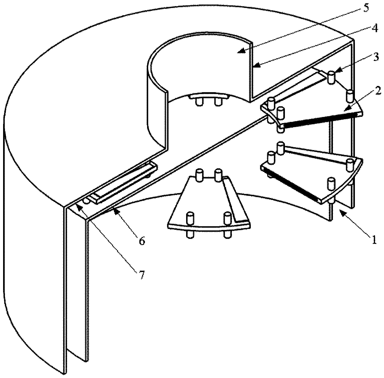
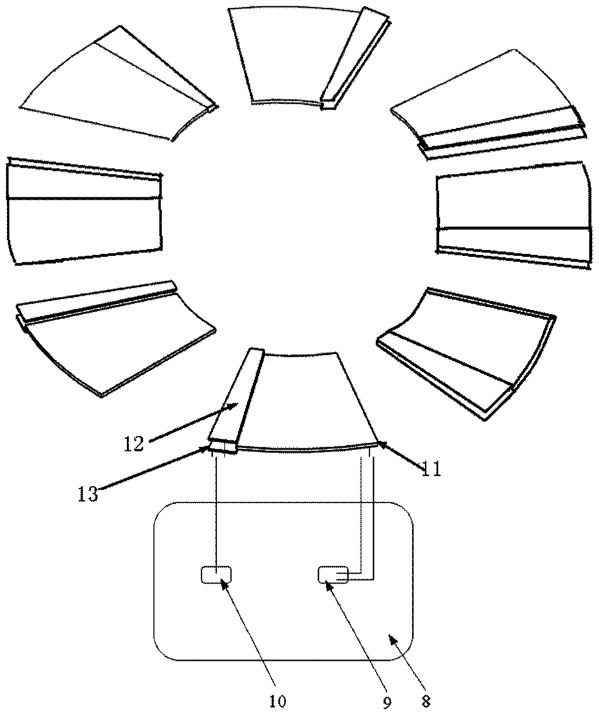
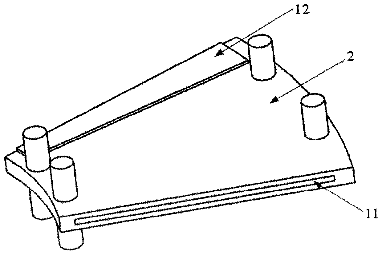
[0065] This embodiment proposes a plasma burner with radial suspension plates, see Figure 1 to Figure 3 , A channel for the radial flow of combustion reactants is formed between the upper end plate 7 and the lower end plate 6 of the burner, and the axial distance between the suspension plate and the upper and lower end plates of the burner is 3 mm. Such as figure 1 As shown, the suspension plate 2 is arranged in the flow channel between the upper and lower end plates along the radial direction, and the suspension plate support column 3 fixes the suspension plate 2 between the upper and lower end plates of the burner. The number of suspension boards 2 is 8, uniformly distributed along the circumferential direction, and there is one high-voltage power supply 8 . Such as figure 2 As shown, the ground electrode 11 of the plasma actuator is embedded in the suspension plate and connected to the ground terminal 10 of the high voltage power supply 8; as image 3 As shown, the hig...

Embodiment 2

[0069] This embodiment proposes a plasma burner with a radial suspension plate. For the purpose of brief description, the same technical features as those used in the above-mentioned embodiment 1 will not be repeated. See Image 6 , is a schematic diagram of the electrode distribution structure of a single set of plasma actuators in the burner proposed in this embodiment, that is, in a single cycle, three suspension plates fixed with ion source actuators are arranged along the radial direction of the burner, and the adjacent suspension plates staggered by 30° in the circumferential direction. The advantages of this are as follows: the plasma exciter is staggered at a certain angle, which can make the effect of plasma excitation uniformly distributed along the circumferential direction, which helps to enhance the effect of plasma excitation, make the flow more uniform and stable, and thus make the flame more stable. Figure 7 for Image 6 Schematic diagram of the full cycle o...


PUM


Abstract

The invention discloses a burner. The burner comprises an upper end plate, a lower end plate, at least one high-voltage power supply, n suspension plates, and n plasma exciters respectively fixed on the n suspension plates, wherein a convex outlet is formed in the center position of the upper end plate for enabling a fluid flowing between the upper end plate and the lower end plate to flow out; the n suspension plates are radially distributed in space between the upper end plate and the lower end plate; the n plasma exciters are connected to the at least one high-voltage power supply for generating plasmas; and n is an integer greater than and equal to 1. When the plasma exciters communicate with high voltage to generate the plasmas, the plasmas are induced to flow to form free jet at the tail edges of the suspension plates, so that dissipation of the momentum of inducing the plasmas to flow by wall surface boundary layers is eliminated, and the excitation strength of the plasmas can be effectively improved.

Description

technical field [0001] The invention belongs to the technical field of combustion devices, and more specifically relates to a plasma burner with a radial suspension plate. Background technique [0002] Gas turbines are widely used in electric power, aviation, petrochemical and other industries due to their small size and large output power. Due to the energy crisis and environmental deterioration, it is urgent to develop efficient and clean combustion chambers, which are required to have the characteristics of reliable ignition, stable combustion, high efficiency and low emissions. At present, the problem of environmental pollution in our country is very serious, and it is very urgent to develop clean combustion technology for gas turbines. Gas turbine manufacturers have developed a variety of clean combustion technologies, such as lean premixed combustion technology, dilute-phase premixed pre-evaporation technology, lean oil direct injection technology, and catalytic combu...

Claims


Application Information

Patent Timeline
Patent Type & Authority Patents(China)
IPC IPC(8): F23R3/00F23C99/00
CPCF23C99/001F23C2900/99005F23R3/00F23R2900/00008
Inventor 李钢朱俊强杜薇徐纲卢新根张燕峰尹娟穆勇刘存喜
Owner INST OF ENGINEERING THERMOPHYSICS - CHINESE ACAD OF SCI
Why Eureka
Try Eureka