
Novel high-pressure pump tappet

A high-pressure pump, a new type of technology, used in fuel injection pumps, engine components, machines/engines, etc., can solve the problems of damage to the cylinder block and guide sleeve, stress concentration, high cost of the tappet, and simplify the manufacturing process and assembly process. Reduce the risk of deformation of parts and the effect of firm and compact overall structure

Active Publication Date: 2017-12-15
HANGZHOU XZB TECH
View PDF6 Cites 2 Cited by
  • Summary
  • Abstract
  • Description
  • Claims
  • Application Information

AI Technical Summary

Problems solved by technology

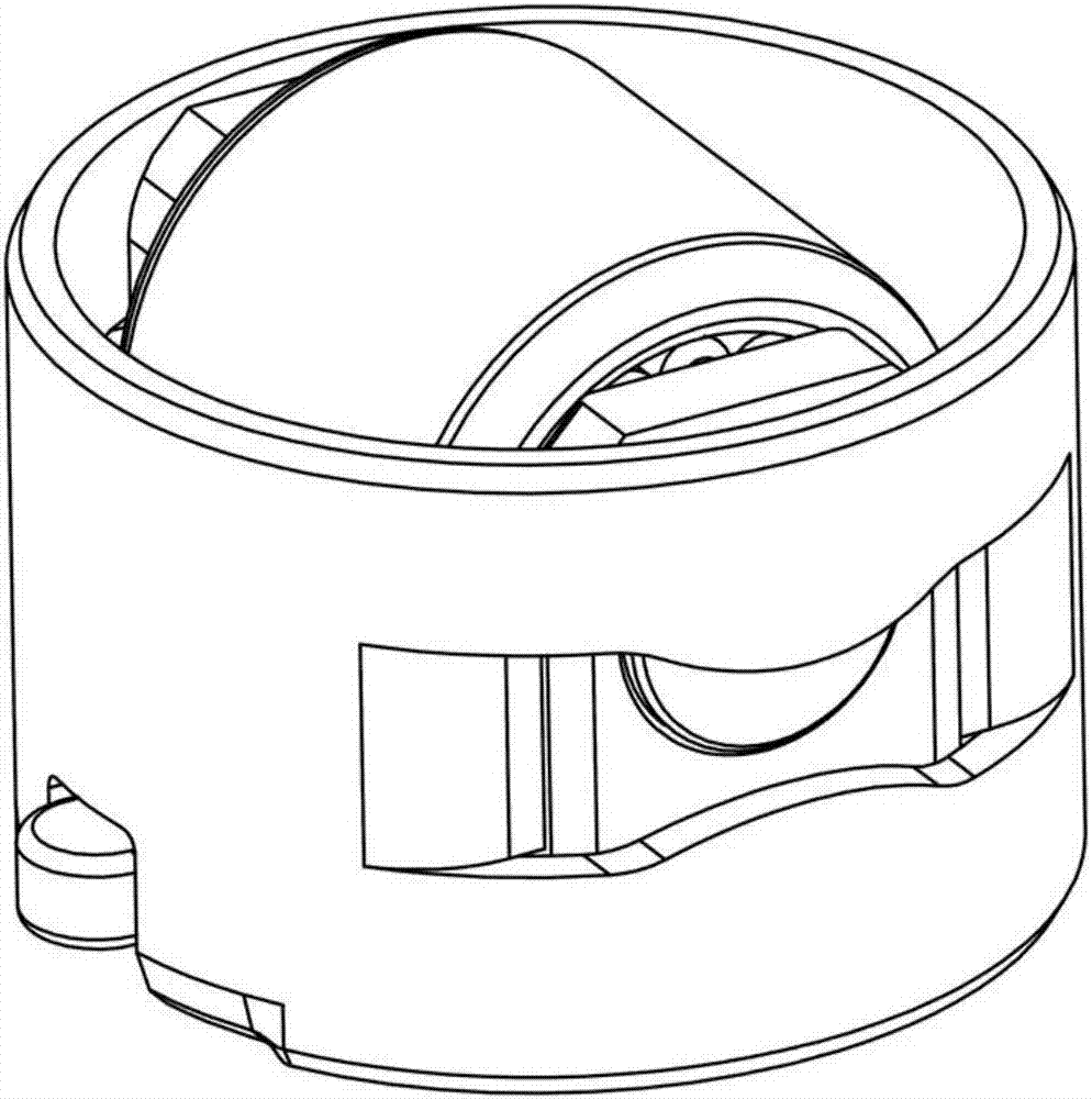
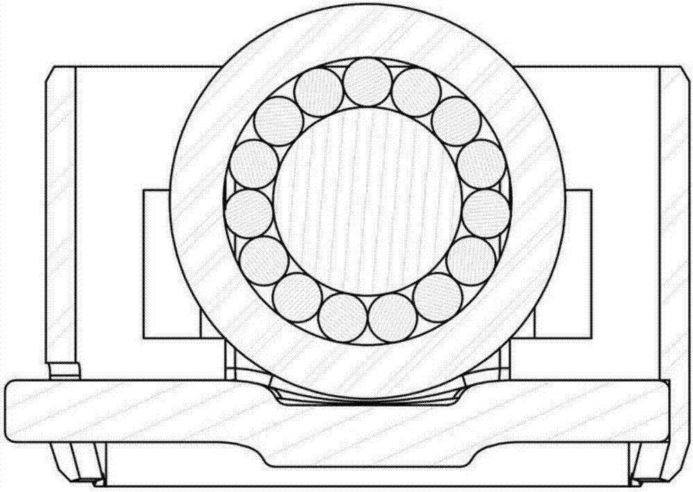
[0003] The existing high-pressure oil pump roller tappet such as figure 1 and figure 2 As shown, the guide sleeve is a cylindrical cylindrical shell, and the limit of the bracket in the guide sleeve is completed by complex processing on the inner wall of the guide sleeve and adding an additional protruding part on the bracket, which is made by complex cold forming. The process is complex and the cost of machining is high, resulting in a high cost of tappets, and the use efficiency of materials cannot be optimized, which is prone to stress concentration, reduces the fatigue strength of the structure, and increases the structural weight of the U-shaped bracket
The guide sleeve is easy to shake in the cylinder body, causing damage to the cylinder body and the guide sleeve; in addition, the existing positioning block is formed by the deformation of the bracket protrusion or the guide sleeve itself. normal work

Method used


Image

  • Novel high-pressure pump tappet
  • Novel high-pressure pump tappet
  • Novel high-pressure pump tappet

Examples


Embodiment Construction

[0036] The present invention will be further described below through specific embodiments and accompanying drawings.

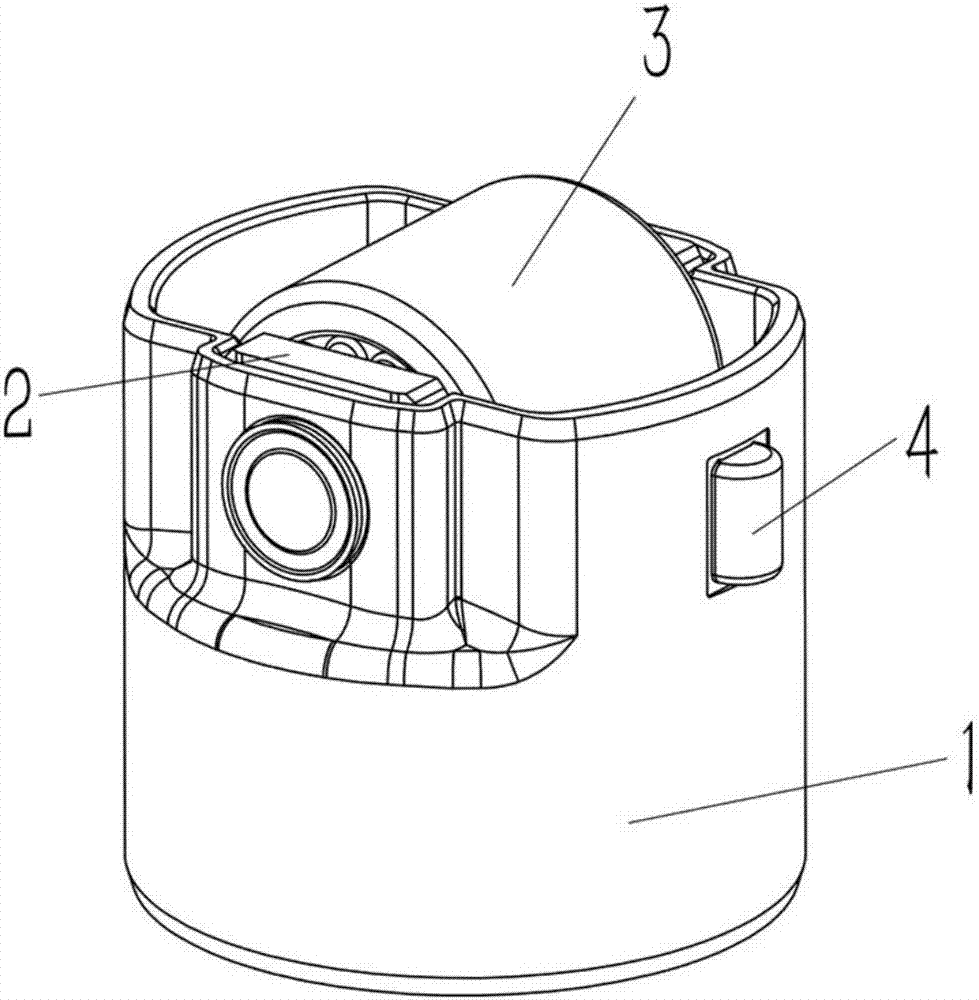
[0037] The implementation method is as follows: image 3 and Figure 4 As shown, a new type of high-pressure pump tappet is used in the engine fuel injection system. The roller tappet includes a guide sleeve 1, a U-shaped bracket 2, a pin roller set 3 and a positioning block 4, and the pin roller set 3 is installed On the U-shaped bracket 2, the U-shaped bracket 2 is installed in the guide sleeve 1, wherein: combined Figure 7 As shown, the U-shaped bracket 2 includes a base plate 2.1 and side plates 2.4 located on the left and right sides of the base plate 2.1, the symmetrical positions on the two side plates 2.4 are provided with shaft holes 2.3, and the front and rear sides 2.4 of the base plate 2.1 are transitions designed for equal strength curve. In the middle of the bottom plate 2.1 of the U-shaped bracket 2, a boss 2.5 protruding downward is provide...


PUM

PropertyMeasurementUnit
Widthaaaaaaaaaa
Lengthaaaaaaaaaa

Abstract

A novel high-pressure pump tappet is used for an engine oil injection system. The roller tappet comprises a guide sleeve, a U-shaped support, a pin shaft roller external member and a locating block. The pin shaft roller external member is mounted on the U-shaped support, the U-shaped support is installed in the guide sleeve and comprises a bottom plate and side plates located on the left and on the right of the bottom plate, and shaft holes are formed in the symmetrical positions of the two side plates. The left side and the right side of the guide sleeve are extruded inwards to form extruded side walls, the two sides of each extruded side wall are provided with limiting side walls being folded inwards, the two side plates of the U-shaped support are arranged in a half-frame-type area composed of the extruded side walls and the limiting side walls, and round holes are formed in the positions, corresponding to the shaft holes, of the extruded side walls. The number of parts of the novel high-pressure pump tappet of the structure is small, the guide sleeve and the U-shaped support are integrally formed, the integral strength is high, the weight is small, motion inertia force can be effectively reduced, friction and abrasion are reduced, work stabilization is realized, and engine efficiency is improved.

Description

technical field [0001] The invention relates to the technical field of engine equipment, in particular to a novel high-pressure pump tappet. Background technique [0002] The roller tappet is an important part of an automobile engine that uses a high-pressure oil pump system. It is installed between the drive cam and the tappet, and converts the rotational motion of the drive cam into a linear reciprocating motion while pushing the tappet to move. The main structure includes a guide sleeve , brackets, rollers and pins. [0003] Existing high-pressure oil pump roller tappets such as figure 1 and figure 2 As shown, the guide sleeve is a cylindrical cylindrical shell, and the limit of the bracket in the guide sleeve is completed by complex processing on the inner wall of the guide sleeve and adding an additional protruding part on the bracket, which is made by complex cold forming. The process is complicated and the machining cost is high, which leads to high cost of tappet...

Claims


Application Information

Patent Timeline
IPC IPC(8): F02M59/10
CPCF02M59/102
Inventor 徐纳董华
Owner HANGZHOU XZB TECH
Learn More