Self-locking type power cable plugging connector

A plug-in connector and power cable technology, which is applied in the field of self-locking power cable plug-in connectors, can solve the problems of no self-locking device and function, large volume, installation and operation errors, etc.

Active Publication Date: 2017-12-12
河北哥伦普勒电气设备有限公司
View PDF9 Cites 2 Cited by
  • Summary
  • Abstract
  • Description
  • Claims
  • Application Information

AI Technical Summary

Problems solved by technology

[0002] When the existing three-phase power cables are connected to underground power transformers, oil-immersed load switches and other equipment, they generally adopt the combination method of multi-component assembly. There are many parts and large volume, and the installation and maintenance are complicated and inconvenient.
Chinese patent No. 200420020971.4 discloses a "buried transformer high-voltage cable connector" and patent No. 200610036340.5 discloses a "three-phase power cable connector". Although the components are small but numerous, and the high-voltage live parts have low compressive strength, they need to be isolated by plastic insulating brackets and filled with insulating media to pass the AC withstand voltage test; and the two connectors do not have self-locking devices and functions for limiting positions. In actual use, it is difficult for construction personnel to grasp whether the two connectors are properly connected, and errors in installation operations are prone to occur, which will bring certain economic losses to the normal operation of the equipment.

Method used


Image

  • Self-locking type power cable plugging connector
  • Self-locking type power cable plugging connector
  • Self-locking type power cable plugging connector

Examples


Embodiment Construction

[0022] The following will clearly and completely describe the technical solutions in the embodiments of the present invention with reference to the accompanying drawings in the embodiments of the present invention. Obviously, the described embodiments are only some, not all, embodiments of the present invention. Based on the embodiments of the present invention, all other embodiments obtained by persons of ordinary skill in the art without making creative efforts belong to the protection scope of the present invention.

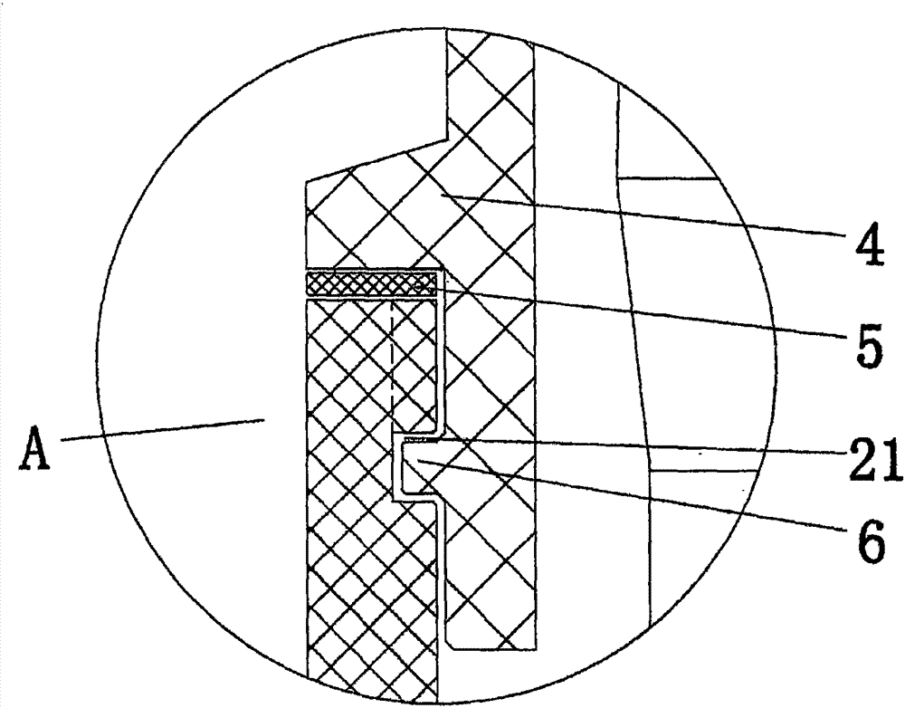
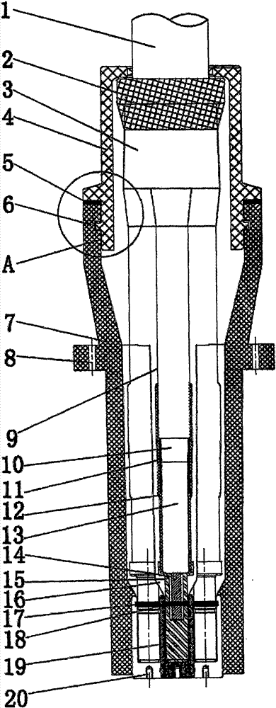
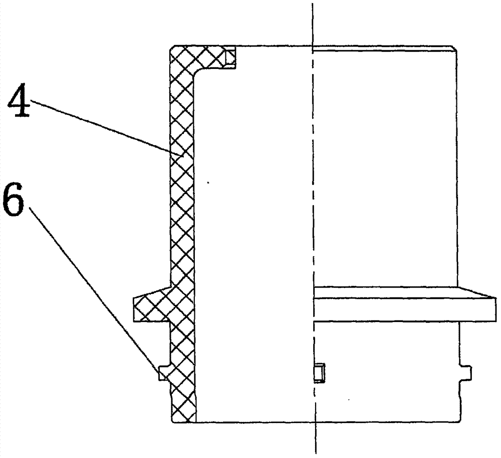
[0023] see Figure 1-8 , the present invention provides a technical solution: a self-locking power cable plug connector, including a plug-in base 7 and a fixed sealing cover 4, a positioning groove 21 is opened in a cavity at one end of the plug-in base 7, and four of the plug-in base 7 The corners are all provided with socket fixing holes 8, the fixed sealing cover 4 is provided with a fixed sealing cover slot 6, the fixed sealing cover slot 6 is located in t...


PUM


Abstract

The invention discloses a self-locking type power cable plugging connector. The self-locking type power cable plugging connector comprises an inserting piece base and a fixed sealing cover; a positioning groove is formed in a cavity in one end of the inserting piece base; a fixed sealing cover clamping groove is formed in the fixed sealing cover; a power cable conductor is sleeved with a power cable semi-conductive layer; the bottom of the power cable conductor is sleeved with a power cable insulating layer; the bottom of a power cable outer sheath layer is sleeved with a cable auxiliary semi-conductive layer and a cable auxiliary insulating layer from inside to outside in sequence; a spring contact finger mounting groove is formed in the upper end surface of a concave type metal socket; a conductive buffer groove and a self-locking limiting groove are formed in a convex type inserting piece from the top to bottom in sequence; and the spring contact finger mounting groove and the metal spring contact finger are in interference fit. The self-locking type power cable plugging connector has a small size, self-locking function plugging connection characteristic and high voltage resistance, and the main body, without using other parts and medium, can pass an alternating current voltage withstand test to be suitable for an underground type transformer, a fully-sealed oil switch and SF<6> electrical equipment.

Description

technical field [0001] The invention relates to the technical field of electrical equipment for power cables, in particular to a self-locking power cable plug connector. Background technique [0002] When the existing three-phase power cables are connected to underground power transformers, oil-immersed load switches and other equipment, they generally adopt the combination method of multi-component assembly. There are many parts and large volume, and the installation and maintenance are complicated and inconvenient. Chinese patent No. 200420020971.4 discloses a "buried transformer high-voltage cable connector" and patent No. 200610036340.5 discloses a "three-phase power cable connector". Although the components are small but numerous, and the high-voltage live parts have low compressive strength, they need to be isolated by plastic insulating brackets and filled with insulating media to pass the AC withstand voltage test; and the two connectors do not have self-locking devi...

Claims


Application Information

Patent Timeline
IPC IPC(8): H01R13/15H01R13/17H01R13/639
CPCH01R13/15H01R13/17H01R13/639
Inventor 邱健武刘峰李思蔚潘伟刘洋
Owner 河北哥伦普勒电气设备有限公司
Why Eureka
Try Eureka