Eureka AIR delivers breakthrough ideas for toughest innovation challenges, trusted by R&D personnel around the world.

Projection system and illumination system

A technology of lighting system and projection system, applied in the field of lighting system, can solve the problems of high manufacturing cost, complicated manufacturing method of lighting system structure, large manufacturing process tolerance, etc.

Inactive Publication Date: 2017-12-12
CORETRONIC
View PDF6 Cites 1 Cited by
  • Summary
  • Abstract
  • Description
  • Claims
  • Application Information

AI Technical Summary

Problems solved by technology

As each model is different, the mechanism design may face many problems due to the limitation of the overall casing size: 1. The structure of the lighting system and its manufacturing method are complicated, 2. The production cost is high, 3. The process tolerance is large

Method used


Image

  • Projection system and illumination system
  • Projection system and illumination system
  • Projection system and illumination system

Examples


Embodiment Construction

[0020] The foregoing and other technical contents, features and effects of the present invention will be clearly presented in the following detailed description of a preferred embodiment with reference to the accompanying drawings. The directional terms mentioned in the following embodiments, such as: up, down, left, right, front or back, etc., are only referring to the directions of the drawings. Accordingly, the directional terms are used to illustrate and not to limit the invention.

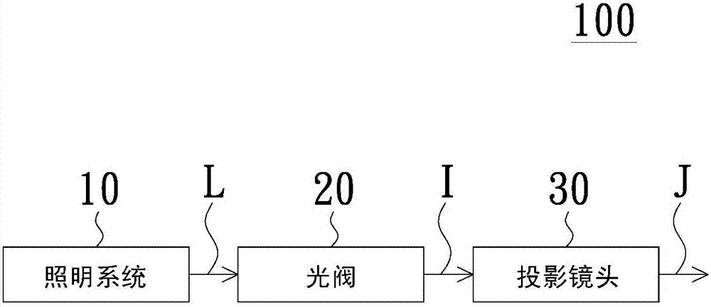
[0021] see figure 1 , the projection system 100 of the embodiment of the present invention includes an illumination system 10 , a light valve 20 and a projection lens 30 . The illumination system 10 is used to provide an illumination light beam L. As shown in FIG. The light valve 20 is located on the transmission path of the illuminating light beam L, and converts the illuminating light beam L into an image light beam I. The projection lens 30 is located on the transmission path of the imag...


PUM


Abstract

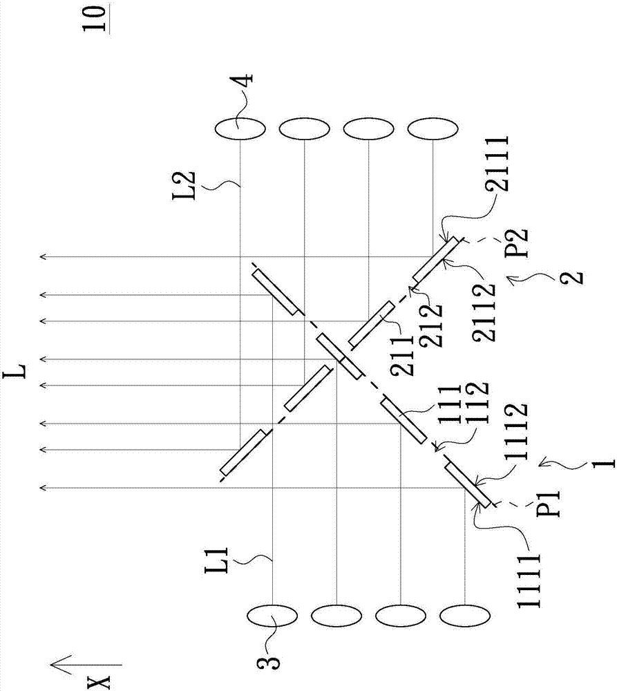
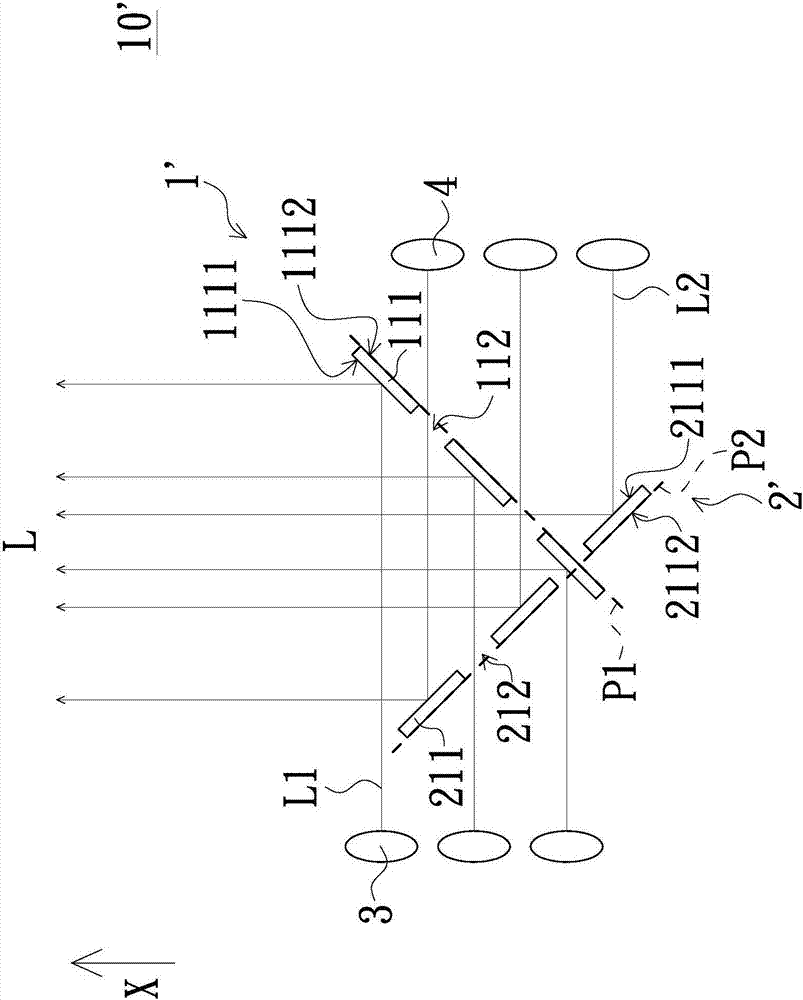
The invention discloses a projection system, and the system comprises a first illumination integration element, a second illumination integration element, a plurality of first light source elements, and a plurality of second light source elements. The first illumination integration element is provided with a plurality of first light reflection regions which are separated from each other and are located on a first plane. The second illumination integration element is provided with a plurality of second light reflection regions which are separated from each other and are located on a second plane. The second plane is not parallel to the first plane. The first light source elements provide first light beams. The first light reflection regions are located on the transmission path of the first light beams, and the first light beams are reflected by the first light reflection regions and then move forwards in an illumination direction. The second light source elements provide second light beams. The second light reflection regions are located on the transmission path of the second light beams, and the second light beams are reflected by the second light reflection regions and then move forwards in an illumination direction. The illumination system is good in optical quality, and the projection system is good in imaging quality.

Description

technical field [0001] The present invention relates to an illumination system, in particular to an illumination system applied to a projection system. Background technique [0002] At present, the proportion of projectors using light sources such as lasers in the high-end projector market is getting higher and higher, and there is a demand for higher and higher brightness at the same time. In order to achieve higher brightness, it is also necessary to add more light sources in the projector. Due to the restriction on the arrangement of multiple light sources, multiple light source elements will be clustered and arranged in two different directions, and then the light combining elements will be used to gather the light and then guide it into the light combining system of the projector. As each model is different, the design of the mechanism may be limited by the size of the overall casing, so it faces many problems: 1. The structure of the lighting system and its manufactur...

Claims


Application Information

Patent Timeline
Patent Type & Authority Applications(China)
IPC IPC(8): G03B21/20
CPCG03B21/2013G03B21/2066G03B21/2033F21V7/0066
Inventor 吴宣毅王纪勋邱浩玮陈科顺
Owner CORETRONIC
Why Eureka
Eureka Blog
Learn More