Optical lever measuring device
A technology of measuring devices and optical levers, applied in measuring devices, optical devices, instruments, etc., can solve problems such as unfavorable laboratory utilization efficiency, inability to observe changes in readings, inconvenient operation and readings, etc., to increase measurement sensitivity and Accuracy, small footprint, and high measurement accuracy
- Summary
- Abstract
- Description
- Claims
- Application Information
AI Technical Summary
Problems solved by technology
Method used
Image
Examples
Embodiment 1
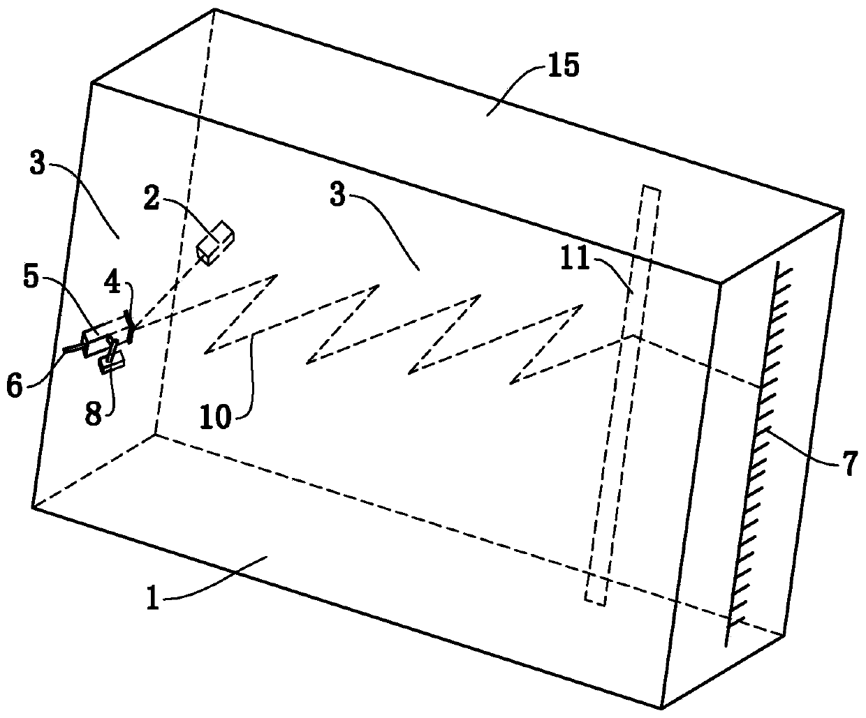
[0050] like Figure 1 to Figure 3 Commonly shown, a kind of optical lever measuring device comprises base plate 1, top plate 15, laser device 2, two mirrors 3 parallel to each other, mirror 4, connecting frame 5, supporting foot 6, display screen 7 with scale and The support 8, the two reflective mirrors 3 and the display screen 7 are all arranged vertically on the bottom plate 1, the top plate 15 is arranged between the tops of the two reflective mirrors 3, and the reflective surfaces of the two reflective mirrors 3 are oppositely arranged.
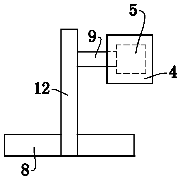
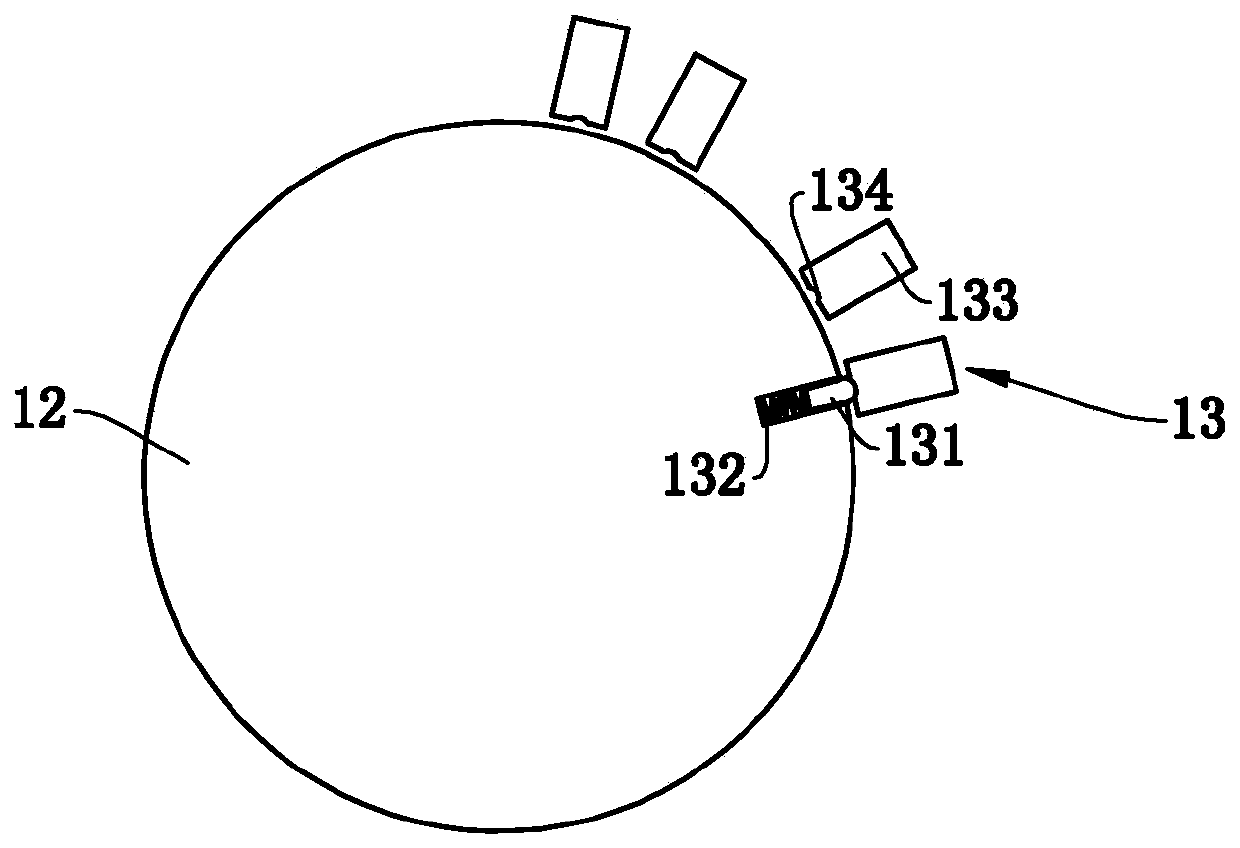
[0051] The support 8 is fixedly installed on a reflector 3, and a horizontal axis 9 is arranged between the connecting frame 5 and the support 8. One end of the connecting frame 5 is fixedly connected to the reflector 4, and the other end is fixedly connected to the supporting foot 6, and the supporting foot 6 and the reflection The mirror 4 is located on both sides of the reflective mirror 3 respectively, and the reflective surface of t...
Embodiment 2
[0069] This embodiment is basically the same as Embodiment 1, the difference is that, as Figure 7 As shown, the reflective surface of the laser display position adjustment mirror 11 is a plane, and the optical path 10 between the laser display position adjustment mirror 11 and the display screen 7 is also provided with a laser inline display mirror 14, and the laser inline display mirror 14 is opposite to the laser beam. Perform horizontal widening, such as Figure 8 As shown, the laser is displayed horizontally on the display screen 7, which facilitates the reading.
[0070] Preferably, the laser inline display mirror 14 is a Powell inline lens.
Embodiment 3
[0072] This embodiment is basically the same as Embodiment 1, the difference is that, as Figure 9 As shown, the top plate 15 is provided with a guide rail 16, of course, the guide rail 16 can also be installed on the bottom plate 1, the extension direction of the guide rail 16 is consistent with the extension direction of the reflective mirror 3, and the laser display position adjustment mirror 11 is slidably installed on the guide rail 16 . In this way, the position of the laser display position adjustment mirror 11 can be changed conveniently, and the problem that the laser light path deviates from the range of the laser display position adjustment mirror 11 due to changing the laser reflection angle can be avoided.
[0073] The reflective surface of the laser display position adjustment mirror 11 is a plane, the guide rail 16 is provided with a slide block 17, an angle adjustment device 18 is provided between the laser display position adjustment mirror 11 and the slide bl...
PUM
 Abstract
Description
Claims
Application Information
 - R&D
- Intellectual Property
- Life Sciences
- Materials
- Tech Scout
- Unparalleled Data Quality
- Higher Quality Content
- 60% Fewer Hallucinations
Browse by: Latest US Patents, China's latest patents, Technical Efficacy Thesaurus, Application Domain, Technology Topic, Popular Technical Reports.
© 2025 PatSnap. All rights reserved.Legal|Privacy policy|Modern Slavery Act Transparency Statement|Sitemap|About US| Contact US: help@patsnap.com


