Automatic oil spraying device for bolt holes of engine bodies

A technology of engine body and fuel injection device, which is applied in the direction of engine components, engine lubrication, mechanical equipment, etc. It can solve problems such as unguaranteed lubrication effect, inaccurate nozzle positioning, and poor lubrication effect, so as to improve atomization effect and lubricate The effect of good effect and good lubricating effect

Inactive Publication Date: 2017-12-12
WEIFANG VOCATIONAL COLLEGE
View PDF0 Cites 2 Cited by
  • Summary
  • Abstract
  • Description
  • Claims
  • Application Information

AI Technical Summary

Problems solved by technology

[0003] (1) Lubrication by fixed oil dripping device: most of the lubricating oil drops to the bottom of the bolt hole, the lubricating effect is poor, and the positioning of the oil nozzle is not accurate, and the lubricating oil is seriously wasted
[0004] (2) Lubrication with an oil pot manually: the amount of oil injected is unstable, and the lubrication effect cannot be guaranteed
There are many bolt holes, the amount of manual labor is large, and it takes a long time

Method used


Image

  • Automatic oil spraying device for bolt holes of engine bodies
  • Automatic oil spraying device for bolt holes of engine bodies
  • Automatic oil spraying device for bolt holes of engine bodies

Examples


Embodiment 1

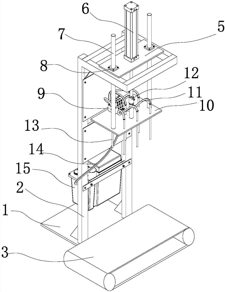
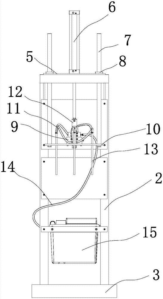
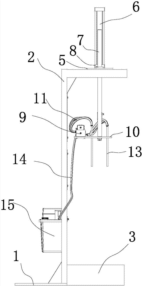
[0045] Such as Figure 1 to Figure 10 As shown, the engine body bolt hole automatic fuel injection device according to the present invention includes a frame 2, a fixed plate 5 is arranged on the frame 2, a driving device is arranged on the fixed plate 5, and the working end of the driving device passes through the fixed plate 5 and is connected. Skateboard 10, the slideboard 10 is provided with an oil-air mixer 9, the output end of the oil-air mixer 9 communicates with the nozzle 13 through the first hose 11, the nozzle 13 is installed through the skateboard 10, and the input end of the oil-air mixer 9 communicates with the lubrication through the second hose 14 pump 15.

[0046] The lubricating pump 15 can be fixed to the frame 2 , and the lubricating pump 15 can also be fixed to the slide plate 10 . The driving device can be an air cylinder 6 or an electric cylinder.

[0047] The bottom of the frame 2 can be provided with a base 1 to ensure that the automatic fuel injecti...

Embodiment 2

[0050] Such as Figure 1-Figure 4 As shown, the slide plate 10 is provided with a guide shaft 7 , and the guide shaft 7 is arranged through the fixed plate 5 . A linear bearing 8 may be provided at the joint between the guide shaft 7 and the fixed plate 5 . The friction between the guide shaft 7 and the fixed plate 5 is reduced, a good guiding effect of the guide shaft 7 is ensured, and the movement accuracy of the slide plate 10 is improved. The number of guide shafts 7 can be set according to needs, and the effect of setting 2, 3, and 4 guide shafts 7 is better, which can increase the accuracy of the guiding effect, and at the same time, will not increase the movement resistance. The guide shaft 7 can guide the movement of the slide plate 10 to ensure that the movement direction of the slide plate 10 is accurate and that the nozzle 13 can be accurately inserted into the bolt hole. All the other are the same as embodiment one.

Embodiment 3

[0052] Such as Figure 1-Figure 4 As shown, slide rails and slide blocks that cooperate with each other are provided between the slide plate 10 and the frame 2 . It can further enhance the moving accuracy of the sliding board 10 and reduce unstable factors such as vibration during the moving process of the sliding board 10 . All the other are with embodiment two.


PUM


Abstract

The invention relates to an automatic fuel injection device for bolt holes of an engine body, belonging to the technical field of engine supporting equipment. It includes a frame with a fixed plate on the frame, a drive device on the fixed plate, the working end of the drive device runs through the fixed plate and connects to the slide plate, an oil-air mixer is installed on the slide plate, and the output end of the oil-air mixer is connected to the nozzle through the first hose , the spray head is set through the slide plate, and the input end of the oil-air mixer is connected to the lubricating pump through the second hose. The invention can accurately penetrate into the bolt holes for atomized oil injection lubrication, has good lubricating effect, less oil consumption, automatic lubrication and high efficiency.

Description

technical field [0001] The invention relates to an automatic fuel injection device for bolt holes of an engine body, belonging to the technical field of engine supporting equipment. Background technique [0002] During the engine assembly process, the main bolt holes of the engine body and the crankcase main bolts need to be lubricated before the joint process, otherwise the bolt bonding phenomenon will occur. At present, the following two methods are mainly used for lubrication: fixed oil dripping device for lubrication and manual lubrication with oil pot. The defects of these two lubrication methods are as follows: [0003] (1) Lubrication by a fixed oil dripping device: most of the lubricating oil drops to the bottom of the bolt hole, the lubricating effect is poor, and the positioning of the oil nozzle is not accurate, and the lubricating oil is seriously wasted. [0004] (2) Manual lubrication with an oil pot: the amount of oil injected is unstable, and the lubricatio...

Claims


Application Information

Patent Timeline
Patent Type & Authority Applications(China)
IPC IPC(8): F16N7/32F16N7/34F16N21/02
CPCF16N7/32F16N7/34F16N21/02
Inventor 冯加锋杜洪香王雷
Owner WEIFANG VOCATIONAL COLLEGE
Why Eureka
Try Eureka