
Improved type graduated circle difference speed reduction device

A technology of reduction gear and indexing circle, which is applied in the direction of transmission, transmission parts, gear transmission, etc., can solve the problems such as the inability to realize the manufacture and assembly of the reducer, the high cost of the motor and the small reduction ratio, etc. The effect of smooth operation and reduced speed requirements

Pending Publication Date: 2017-12-12
马墉良 +1
View PDF10 Cites 2 Cited by
  • Summary
  • Abstract
  • Description
  • Claims
  • Application Information

AI Technical Summary

Problems solved by technology

But the disadvantage is that the deceleration ratio is small, the minimum single-stage deceleration is 3, and the maximum is generally not more than 10, and the accuracy of deceleration will be doubled for each additional stage, and the volume will also increase
[0006] Although someone invented the indexing circular difference reducer, the transmission ratio is too large, and the manufacture and assembly of the reducer cannot be realized. When the same output speed is required, a higher speed requirement is put forward for the speed of the motor shaft. The higher the speed of the motor, the higher the cost. For some manufacturers, the cost of the motor is relatively high, and the cost performance is relatively low.

Method used


Image

  • Improved type graduated circle difference speed reduction device
  • Improved type graduated circle difference speed reduction device
  • Improved type graduated circle difference speed reduction device

Examples


Embodiment Construction

[0032] In order to facilitate the understanding of those skilled in the art, the present invention will be further described below in conjunction with the embodiments and accompanying drawings, and the contents mentioned in the embodiments are not intended to limit the present invention.

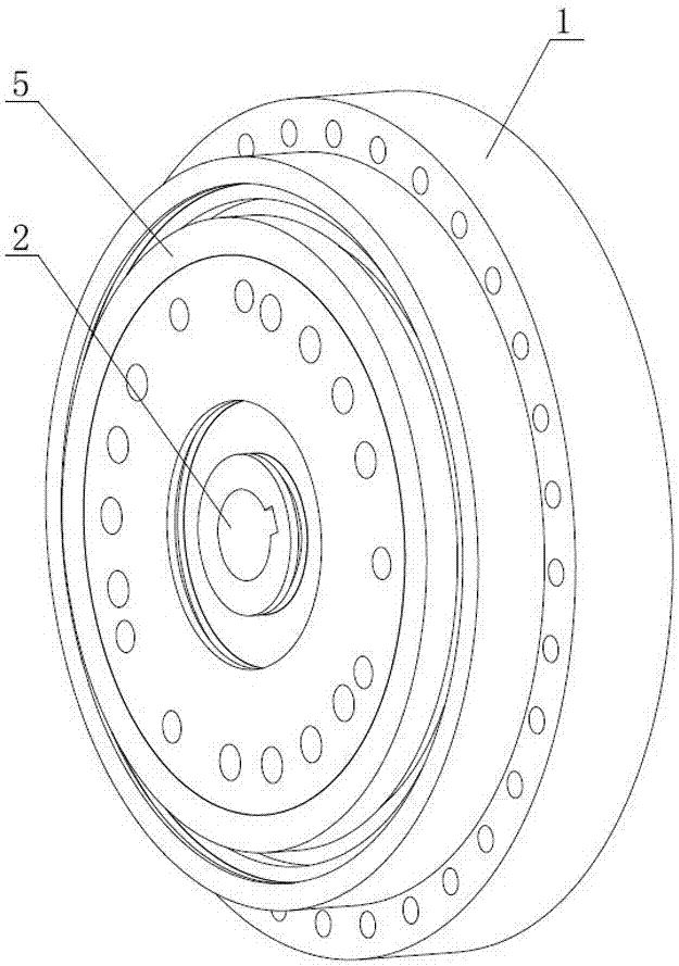
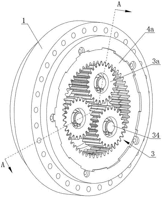
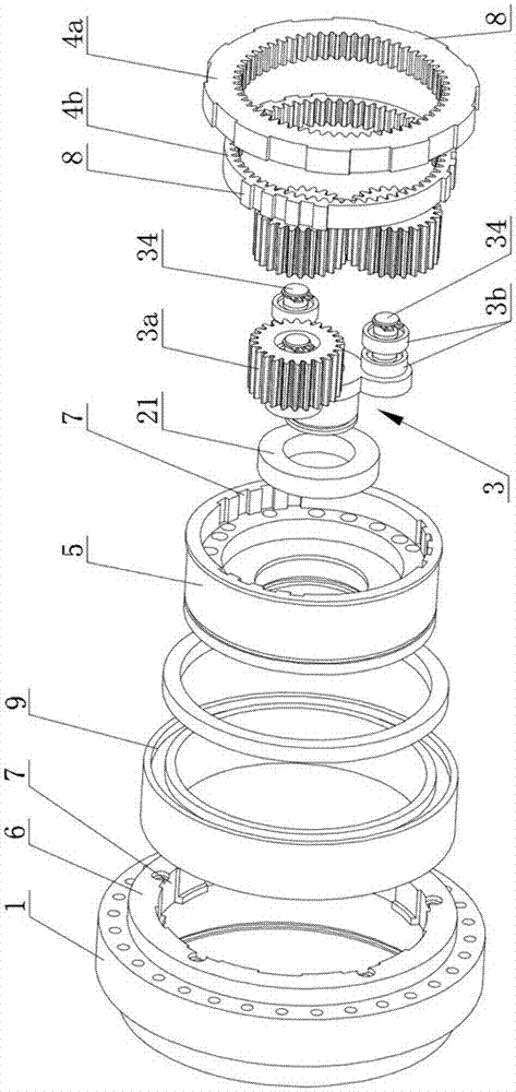
[0033] Such as Figure 1 to Figure 5 Shown is the first embodiment of the improved indexing circular differential reducer, including the installation body 1, the input shaft sleeve 2, the planetary gear set 3, the output sleeve 4 and the first inner ring gear 4a, the output sleeve 4 is provided with the first Two inner ring gears 4b, the planetary gear set 3 includes a main planetary gear 31, an auxiliary planetary gear 32 coaxially fixedly connected with the main planetary gear 31, and a planetary carrier 33 for supporting the main planetary gear 31 and the auxiliary planetary gear 32 , the input bushing 2 is integrally formed with the planetary gear carrier 33, the main planetary gear 31 i...


PUM


Abstract

The invention relates to the technical field of speed reduction transmission, in particular to an improved type graduated circle difference speed reduction device which comprises a mounting body, an input shaft sleeve, a planetary gear group, an output circular sleeve and a first inner gear ring; the output circular sleeve is provided with a second inner gear ring; the mounting body is provided with a gear ring mounting cover which is put together with and fixedly connected with the mounting body; spline grooves are arranged on the inner wall of the gear ring mounting cover and the inner wall of the output circular sleeve respectively; and spline teeth are arranged on the first inner gear ring and the second inner gear ring and are inlaid into the corresponding spline teeth. The invention provides the improved type graduated circle difference speed reduction device which can be actually put on production and processing and is convenient to assemble; and the improved type graduated circle difference speed reduction device is relatively low on requirements for rotational speed of a motor spindle, smooth in running, higher in performance price ratio, small in size and long in service life, has the advantages of high transmission efficiency, convenience in disassembly, good rigidity and high transmission accuracy, is particularly wider in transmission ratio range and is more stronger in maneuverability of producing an adaptive speed reduction device.

Description

technical field [0001] The invention relates to the technical field of reduction transmission devices, in particular to an improved indexing circular difference reduction device. Background technique [0002] In the mechanism currently used to transmit power and motion, the application range of the reducer is quite wide. It can be seen in almost all kinds of mechanical transmission systems. From the transmission of large power to small loads and precise angle transmission, the application of reducers can be seen, and in industrial applications, reducers have The function of deceleration and torque increase, so it is widely used in the conversion equipment of speed and torque. The reducer is a mechanism for power transmission. With the development of industry and the automation of factories, the demand for the use of reducers is increasing. [0003] However, the currently widely used high speed ratio reducer has complex structure, unstable operation, small single-stage tran...

Claims


Application Information

Patent Timeline
Patent Type & Authority Applications(China)
IPC IPC(8): F16H1/32F16H57/021F16H57/023F16H57/08
CPCF16H1/32F16H57/021F16H57/023F16H57/08F16H2001/327F16H2057/02086
Inventor 马墉良
Owner 马墉良
Learn More