Equal-length cutting device for steel plate
A cutting device and equal-length technology, applied in the direction of shearing devices, shearing machine accessories, maintenance and safety accessories, etc., can solve problems such as large errors in soft ruler measurement, operator fatigue, and more time-consuming, etc., to achieve The effect of increasing the force bearing area, facilitating transportation and improving efficiency
- Summary
- Abstract
- Description
- Claims
- Application Information
AI Technical Summary
Problems solved by technology
Method used
Image
Examples
Embodiment 1
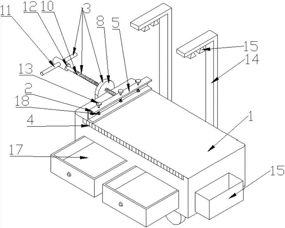
[0029] Such as figure 1 As shown, a steel plate equal-length cutting device in this embodiment includes a horizontal worktable 1, and is provided on the horizontal worktable 1 with a clamping part 2 that can move left and right, and is used to drive the clamping part 2 on the horizontal workbench 1. The driving part 3 that moves left and right, the side of the horizontal table 1 near the top end of the horizontal table 1 is provided with a scale 4 .
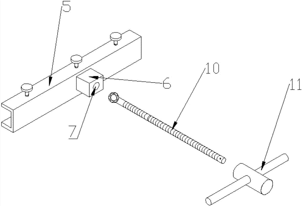
[0030] The clamping part 2 includes a U-shaped steel 5 placed horizontally, the side wall of the U-shaped steel 5 is in contact with the top of the horizontal workbench 1, the back of the U-shaped steel 5 is provided with a raised block 6, and the raised block 6 is provided with a There is a hole 7.
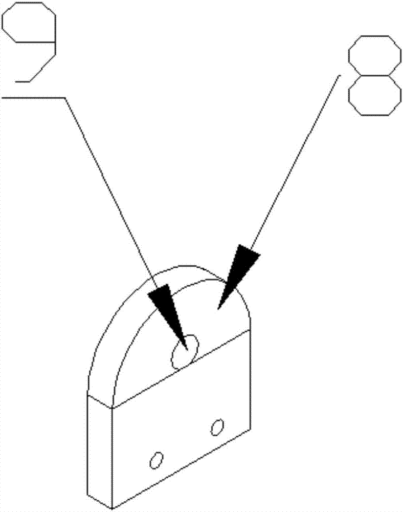
[0031] The driving part 3 includes a fixed seat 8, a threaded rod 10, and a rotating handle 11 fixed on the side of the horizontal workbench 1. The fixed seat 8 is provided with a hole two 9, and the fixed seat 8 is connected with ...
Embodiment 2
[0034] On the basis of Example 1, the other side wall of the U-shaped steel 5 is provided with a channel 4, and the inside of the channel 4 is also provided with an internal thread, and the U-shaped steel 5 is provided with a vertical screw 13. After the vertical screw 13 passes through the tunnel 4 and the U-shaped steel 5, the vertical screw 13 moves up and down to give the U-shaped steel 5 a vertical downward force. By turning the vertical screw 13 up and down, the compression degree of the bottom of the vertical screw 13 to the vertical direction of the locking part 2 can be freely adjusted, so that the locking part 2 is firmer and easier to move.
Embodiment 3
[0036] On the basis of embodiment 1 or embodiment 2, a gasket 18 is provided between the bottom of the vertical screw 13 and the U-shaped steel 5, which increases the stress area between the vertical screw 13 and the U-shaped steel 5, and protects the The top of the vertical screw 13 and the inside of the U-shaped steel 5 prevent damage.
PUM
 Abstract
Description
Claims
Application Information
 - R&D
- Intellectual Property
- Life Sciences
- Materials
- Tech Scout
- Unparalleled Data Quality
- Higher Quality Content
- 60% Fewer Hallucinations
Browse by: Latest US Patents, China's latest patents, Technical Efficacy Thesaurus, Application Domain, Technology Topic, Popular Technical Reports.
© 2025 PatSnap. All rights reserved.Legal|Privacy policy|Modern Slavery Act Transparency Statement|Sitemap|About US| Contact US: help@patsnap.com


