Detachable handcart

A trolley and push rod technology, which is applied in the direction of trolleys, multi-axis trolleys, motor vehicles, etc., can solve the problems of wasting indoor space, occupying three-dimensional space, and non-detachable objects, so as to save indoor space, improve work efficiency, and have a reasonable structure Effect

Inactive Publication Date: 2014-12-24
SHANGHAI HEHUA ELECTRONICS TECH
View PDF1 Cites 0 Cited by
  • Summary
  • Abstract
  • Description
  • Claims
  • Application Information

AI Technical Summary

Problems solved by technology

[0002] With the development of social production and the rapid development of the machinery industry, a large number of industrial tools are produced and used, and the role of trolleys in industrial operations cannot be ignored. The application number is CN 200710025987.2, which discloses a detachable trolley, including at least a folding state and fully expanded state of the cart frame, the first wheel assembly is arranged at the lower front part of the cart frame, and the cart frame includes a push rod, which is rotatably connected to the push rod The front strut at the front end, the material rack whose end is rotatably connected to the push rod, and the connecting rod, one end of the connecting rod is rotatably connected to the material rack, and the connecting rod The other end of the trolley is rotatably connected to the front strut, and the trolley frame is provided with a locking device; the trolley frame of the trolley forms a four-bar linkage mechanism as a whole, which can be rotated and folded, and the operation is simple and convenient ,The volume of the entire trolley is significantly reduced after folding, which is convenient for storage and can reduce the cost of packaging, storage and transportation. However, the load of the trolley cannot be disassembled, and the push rod cannot be disassembled from the side panels. The entire trolley cannot be disassembled and stacked , occupying three-dimensional space, resulting in waste of interior space

Method used


Image

  • Detachable handcart
  • Detachable handcart

Examples


Embodiment Construction

[0013] In order to make the technical means, creative features, goals and effects achieved by the present invention easy to understand, the present invention will be further described below in conjunction with specific illustrations.

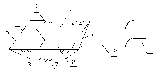
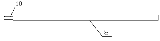
[0014] like figure 1 and figure 2 As shown, a detachable trolley according to the present invention includes a carrier 1, and the carrier 1 includes a bottom plate 2, a front side plate 3, a rear side plate 4, a left side plate 5 and a right side plate 6, and the The base plate 2 is connected with a roller 7, the right side plate 6 is provided with a push rod 8, the front side plate 3 is hinged with the base plate 2, the rear side plate 4 is also hinged with the base plate 2, and the front side plate 3 is hinged with the base plate 2. Both ends of the plate 3 and the rear side plate 4 are provided with card slots 9, the left side plate 5 is respectively connected with the front side plate 3 and the rear side plate 4 through the card slots 9, a...


PUM


Abstract

The invention discloses a detachable handcart which comprises an object carrier. The object carrier comprises a baseplate, a front side plate, a rear side plate, a left side plate and a right side plate, rollers are connected on the baseplate, a push rod is arranged on the right side plate, the front side plate is hinged to the baseplate, the rear side plate is hinged to the baseplate, a clamping groove is formed in each of two ends of each of the front side plate and the rear side plate, the left side plate is connected with the front side plate and the rear side plate through the clamping grooves respectively, the right side plate is connected with the front side plate and the rear side plate through the clamping grooves respectively, the rear side plate and a push rod are in threaded connection, the object carrier is detachable, and the push rod can be demounted from the side plates. When the detachable handcart is not in use, the whole handcart can be demounted and stacked, and only planar space is occupied, so that indoor space is saved greatly. The detachable handcart is reasonable in structure, practical, convenient and suitable for popularization and application.

Description

technical field [0001] The invention relates to the field of industrial machinery, in particular to a detachable trolley. Background technique [0002] With the development of social production and the rapid development of the machinery industry, a large number of industrial tools are produced and used, and the role of trolleys in industrial operations cannot be ignored. The application number is CN 200710025987.2, which discloses a detachable trolley, including at least a folding state and fully expanded state of the cart frame, the first wheel assembly is arranged at the lower front part of the cart frame, and the cart frame includes a push rod, which is rotatably connected to the push rod The front strut at the front end, the material rack whose end is rotatably connected to the push rod, and the connecting rod, one end of the connecting rod is rotatably connected to the material rack, and the connecting rod The other end of the trolley is rotatably connected to the fron...

Claims


Application Information

Patent Timeline
IPC IPC(8): B62B3/02
Inventor 郑小坚郭炎铭
Owner SHANGHAI HEHUA ELECTRONICS TECH
Why Eureka
Try Eureka