Anti-falling device for safety belt hanging
A safety belt and anti-falling technology, applied in safety belts, life-saving equipment, etc., can solve the problems of high falling height and injury to workers, and achieve the effect of reducing injuries and protecting the faller
- Summary
- Abstract
- Description
- Claims
- Application Information
AI Technical Summary
Problems solved by technology
Method used
Image

Examples
Embodiment 1
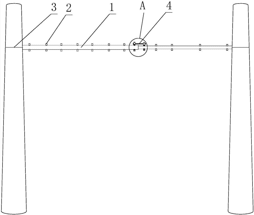
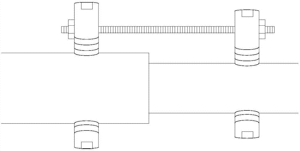
[0028] Such as figure 1 and figure 2 As shown, an anti-falling device for hanging a seat belt includes a cross bar 1, and the two ends of the cross bar 1 are provided with connecting seats 3, and also includes a plurality of segments installed on the cross bar 1 at intervals Seat 2, the segmented seat 2 is a cylindrical structure with external threads provided on the outside, a plurality of internal threaded holes are arranged at intervals on the cross bar 1, and each segmented seat 2 is threadedly connected to the On the cross bar 1, the internally threaded holes are all blind holes, and the length of the segmented seat 2 is longer than the depth of the blind holes.
[0029] This device is used to be fixed between two electric poles: each connecting seat 3 is used for connecting with different electric poles respectively, after completing the connection of this device and corresponding electric pole, it is preferably set that cross bar 1 is positioned at the top of pedal at...
Embodiment 2
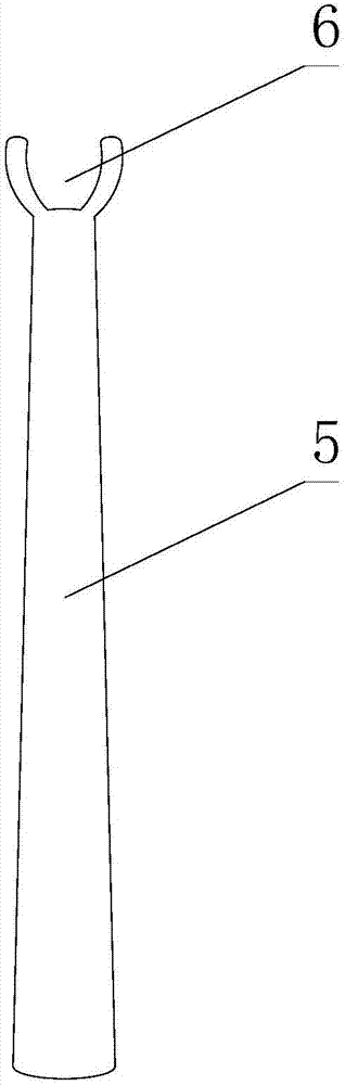
[0033] Such as Figure 1 to Figure 3 As shown, this embodiment is further limited on the basis of Embodiment 1: as a connection seat 3 that is very convenient to connect and separate from the pole, the connection seat 3 includes a steel wire rope and a shackle, One end of the steel wire rope is fixedly connected to the end of the cross bar 1, and the other end of the steel wire rope is wound with a closed collar. Connection of wire rope main body or crossbar 1. In this solution, the collar is used to pass through the shackle, such as the free end of the traction wire rope. After the wire rope wraps around the pole for more than one lap, the collar and the wire rope on the wire rope are connected to the cross bar 1 through the shackle. The connection of the end, the connection of the collar and the cross bar 1, like this, is equivalent to obtaining a self-tightening annular sleeve at each end of the cross bar 1.
[0034]For the convenience of fixing the device at a higher pos...
Embodiment 3
[0042] This embodiment is further limited on the basis of any one of the technical solutions provided by any one of the above embodiments: in order to make the cross bar 1 rotate, this device can also limit the safety belt from sliding freely in the axial direction of the cross bar 1 , along the length direction of the cross bar 1, on the cross bar 1, there are a plurality of installation points for the installation of the segmented seat 2 at intervals, each installation point is provided with a plurality of internal threaded holes, and each installation point A plurality of internally threaded holes are evenly distributed in a circular shape with respect to the axis of the cross bar 1 .
PUM
 Abstract
Description
Claims
Application Information
 - R&D
- Intellectual Property
- Life Sciences
- Materials
- Tech Scout
- Unparalleled Data Quality
- Higher Quality Content
- 60% Fewer Hallucinations
Browse by: Latest US Patents, China's latest patents, Technical Efficacy Thesaurus, Application Domain, Technology Topic, Popular Technical Reports.
© 2025 PatSnap. All rights reserved.Legal|Privacy policy|Modern Slavery Act Transparency Statement|Sitemap|About US| Contact US: help@patsnap.com