Gird-connected current low-frequency harmonic suppression method of cascaded H-bridge medium-voltage converter

A technology of harmonic suppression and converter, applied in AC network to reduce harmonics/ripple, harmonic reduction device, single-network parallel feeding arrangement, etc. Volume increase and other problems, to achieve the effect of improving the quality of grid-connected current and suppressing low-frequency components

Active Publication Date: 2017-12-08
SHANGHAI JIAO TONG UNIV
View PDF1 Cites 7 Cited by
  • Summary
  • Abstract
  • Description
  • Claims
  • Application Information

AI Technical Summary

Problems solved by technology

The first solution is to reduce the bus voltage fluctuation amplitude and suppress its influence by increasing the DC bus capacitance, but this method will lead to a decrease in system dynamic performance and an increase in system cost and volume
The second solution is to use an active filter method, and connect a high-voltage capacitor in parallel with a Buck / Boost circuit next to the supporting capacitor to form a double frequency path. This solution increases the system switching device to increase the loss and increase the system hardware cost.
The third solution is to adjust the parameters of the grid-side control proportional-integral (PI) regulator or add a low-pass filter in the feedback link of the grid-side control system, so that the bandwidth of the grid-side converter control system is lower than the fluctuating voltage frequency. When the fluctuating voltage frequency is low, the bandwidth of the control system needs to be lower, which will lead to a decrease in the dynamic performance of the system
The fourth option is to add a notch filter to the control system, but this fixed-parameter notch filter can only filter out fluctuations of a certain fixed frequency, which is not suitable for medium-voltage converters with fluctuating frequency changes

Method used


Image

  • Gird-connected current low-frequency harmonic suppression method of cascaded H-bridge medium-voltage converter
  • Gird-connected current low-frequency harmonic suppression method of cascaded H-bridge medium-voltage converter
  • Gird-connected current low-frequency harmonic suppression method of cascaded H-bridge medium-voltage converter

Examples


Embodiment Construction

[0039] The present invention will be described in detail below in conjunction with specific embodiments. The following examples will help those skilled in the art to further understand the present invention, but do not limit the present invention in any form. It should be noted that those skilled in the art can make several changes and improvements without departing from the concept of the present invention. These all belong to the protection scope of the present invention.

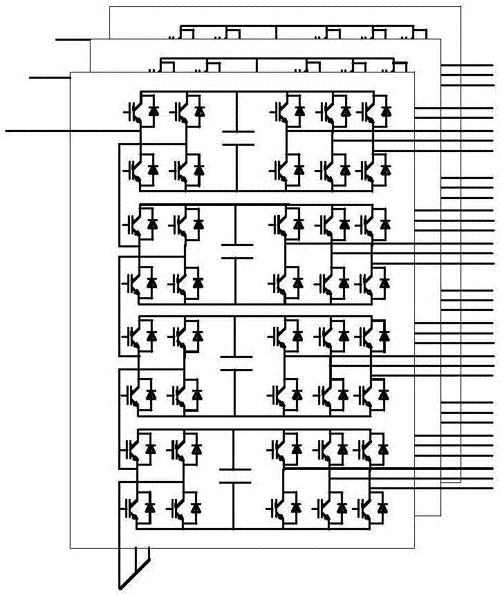
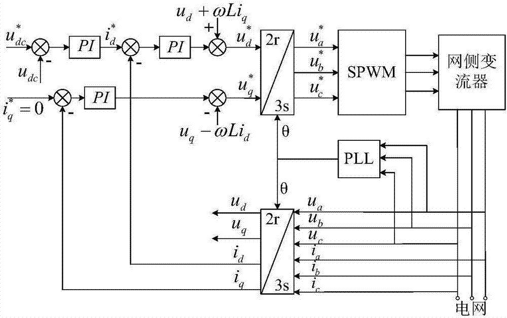
[0040] The invention provides a cascaded H-bridge medium-voltage converter grid-connected current low-frequency harmonic suppression method, wherein the grid-side converters of the cascaded H-bridge medium-voltage converter are multiple three-phase voltage source PWM sub-converters The converter is composed of secondary windings of multi-winding transformers, and there is no coupling between the sub-converters. The DC bus voltage outer loop and current inner loop double closed-loop vector control strateg...


PUM


Abstract

The invention provides a grid-connected current low-frequency harmonic suppression method of a cascaded H-bridge medium-voltage converter. The method is applied to a grid-connected converter. The grid-connected converter comprises a plurality of three-phase voltage source-type pulse width modulation (PWM) sub-converters. The method comprises the step of introducing a second-order frequency conversion trapper into a voltage ring control loop of the three-phase voltage source-type PWM sub-converters to suppress low-frequency harmonics introduced by voltage fluctuation of a DC bus. The influence of the voltage fluctuation of the DC bus of a power module on the grid-connected current is prevented by changing the voltage ring control loop on the condition that a cascaded H-bridge medium-voltage converter system topological structure is not changed, and the quality of the grid-connected current is improved.

Description

technical field [0001] The invention relates to the technical field of converter control, in particular to a method for suppressing low-frequency harmonics of grid-connected current of cascaded H-bridge medium-voltage converters. Background technique [0002] The cascaded H-bridge converter has been popularized and applied in the field of medium voltage variable frequency drive due to its modular design and the characteristics of large-scale production. The grid side of the traditional cascaded H-bridge converter adopts the diode uncontrolled rectification method, and the energy can only flow in one direction, which limits its application range. In order to realize the four-quadrant operation of the converter, the diodes in the converter topology are replaced by insulated gate bipolar transistors (Insulated Gate Bipolar Transistor, IGBT) to form a cascaded H Bridge converter, also known as energy-fed cascaded H-bridge converter, such as figure 1 shown. [0003] Each phase...

Claims


Application Information

Patent Timeline
IPC IPC(8): H02J3/38H02J3/01
CPCH02J3/01H02J3/38Y02E40/40
Inventor 张建文李鑫蔡旭
Owner SHANGHAI JIAO TONG UNIV
Why Eureka
Try Eureka