
Glue injection device of battery

A technology of glue injection device and battery, which is applied to primary batteries, equipment for manufacturing primary batteries, and battery assembly machines, etc., can solve the problem of unrealistically coating the bottom of separator paper, affecting the performance of battery composition, and increasing the amount of glue injected, etc. problems, to achieve the effect of ensuring electrical performance, avoiding performance impact, and high production efficiency

Pending Publication Date: 2017-12-08
ZHONGYIN NINGBO BATTERY CO LTD
View PDF7 Cites 0 Cited by
  • Summary
  • Abstract
  • Description
  • Claims
  • Application Information

AI Technical Summary

Problems solved by technology

[0003] The existing battery glue injection devices generally have the following defects, which lead to the appearance of defective products, that is, the position of the hole in the separator paper at the bottom of the battery steel case is arbitrary, and it must not be centrally located, and because the glue is a fluid with poor fluidity, it is naturally spread evenly. The bottom of the separator paper is not realistic. If you want to ensure that the glue is evenly coated on the bottom of the separator paper after the glue is injected, you need to increase the amount of glue injected, which will lead to too thick glue, which will affect the composition of the battery itself and other performances.

Method used


Image

  • Glue injection device of battery
  • Glue injection device of battery
  • Glue injection device of battery

Examples


Embodiment Construction

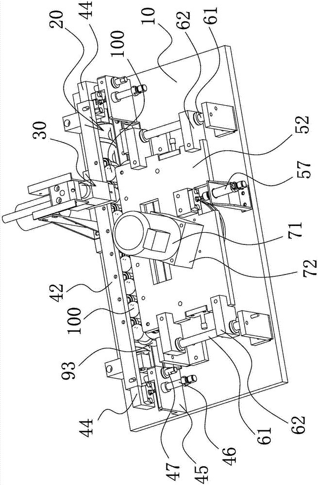
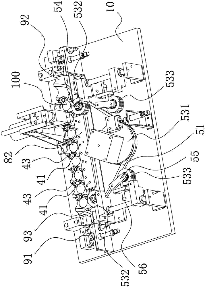
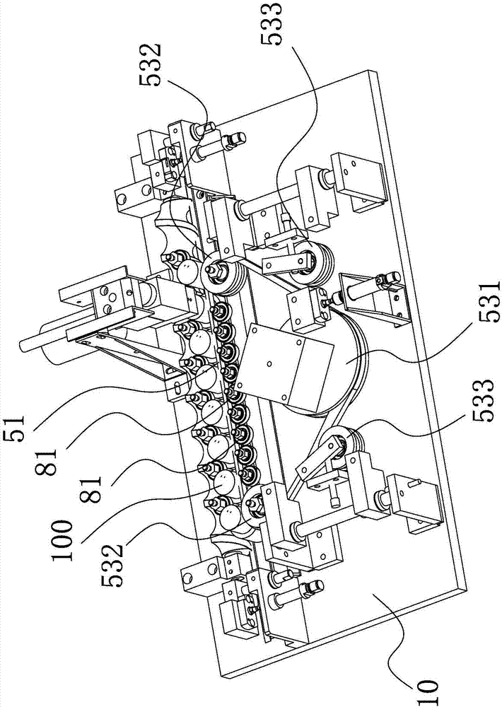
[0026] The following are specific embodiments of the present invention and in conjunction with the accompanying drawings, the technical solutions of the present invention are further described, but the present invention is not limited to these embodiments.

[0027] Due to the poor fluidity of the glue, the uneven coating on the bottom of the separator paper, and if the injection volume of the glue is increased to ensure uniform coating, the glue on the bottom of the battery steel case (the bottom of the separator paper) will be too thick, which will affect the volume and other performance, reducing safety and working life. Therefore, it is necessary to design a more reasonable battery glue injection device that can evenly coat the glue on the bottom of the separator paper.

[0028] Combine below Figure 1 to Figure 3 The technical solution provided by the present invention is described in more detail.

[0029] Such as Figure 1 to Figure 3 As shown, the battery glue injecti...


PUM


Abstract

The invention provides a glue injection device of a battery, and belongs to the technical field of battery production. The glue injection device of the battery comprises a mainboard, a glue injection assembly, a rotation assembly and a transmission assembly, wherein a transmission passage is arranged on the mainboard and is used for transmitting battery steel shells arranged in a line, the glue injection assembly is used for injecting glue into the battery steel shells, the rotation assembly comprises rotation bearings, the rotation bearings are arranged at intervals with the battery steel shells in the transmission passage and are arranged in a line, the whole line of rotation bearings synchronously move and can be near to or far away from the transmission passage, each rotation bearing is clamped into a gap between two corresponding battery steel shells when the whole line of rotation bearings synchronously move, at the moment, an outer wall of each rotation bearing is rotatably connected with outer walls of the two corresponding battery steel shells, the transmission assembly and the rotation assembly are arranged at two sides of the transmission passage, the transmission assembly comprises a transmission belt, the transmission belt is movably arranged and can be near to or far away from the transmission passage, and the transmission belt can be simultaneously in contact with the whole line of battery steel shells and drives the battery steel shells to rotate when getting close to the transmission passage. By the glue injection device of the battery, the glue can be uniformly coated at the bottom of isolation paper.

Description

technical field [0001] The invention belongs to the technical field of battery production and relates to a battery glue injection device. Background technique [0002] In battery production, there is diaphragm paper inside the battery steel case, and occasionally there will be holes at the bottom of the diaphragm paper. In order to ensure airtightness, the battery steel case needs to go through the battery glue injection process. The battery glue injection device is to seal the bottom of the diaphragm paper A mechanism for injecting glue into the steel case of the battery due to leaks. [0003] The existing battery glue injection devices generally have the following defects, which lead to the appearance of defective products, that is, the position of the hole in the separator paper at the bottom of the battery steel case is arbitrary, and it must not be centrally located, and because the glue is a fluid with poor fluidity, it is naturally spread evenly. The bottom of the se...

Claims


Application Information

Patent Timeline
IPC IPC(8): H01M10/04H01M6/00H01M2/14H01M50/403
CPCH01M6/005H01M10/0404H01M50/403Y02P70/50Y02E60/10
Inventor 崔歆薇龚彪常伟范建国蒋增丽虞琪王正雍
Owner ZHONGYIN NINGBO BATTERY CO LTD
Learn More