
Cover

A component and cover technology, applied in the field of cover components, can solve the problems of limited protection function and inconvenient connection, and achieve the effect of maintaining flatness and portability

Active Publication Date: 2017-12-08
ASUSTEK COMPUTER INC
View PDF6 Cites 4 Cited by
  • Summary
  • Abstract
  • Description
  • Claims
  • Application Information

AI Technical Summary

Problems solved by technology

[0006] The purpose of the present invention is to provide a cover assembly to solve the problems of inconvenient connection and limited protection function in existing electronic devices

Method used


Image

  • Cover
  • Cover
  • Cover

Examples


Embodiment Construction

[0019] The specific implementation manner of the present invention will be described in more detail below with reference to schematic diagrams. The advantages and features of the present invention will be apparent from the following description and the scope of the claims. It should be noted that all the drawings are in a very simplified form and use imprecise scales, and are only used to facilitate and clearly assist the purpose of illustrating the embodiments of the present invention.

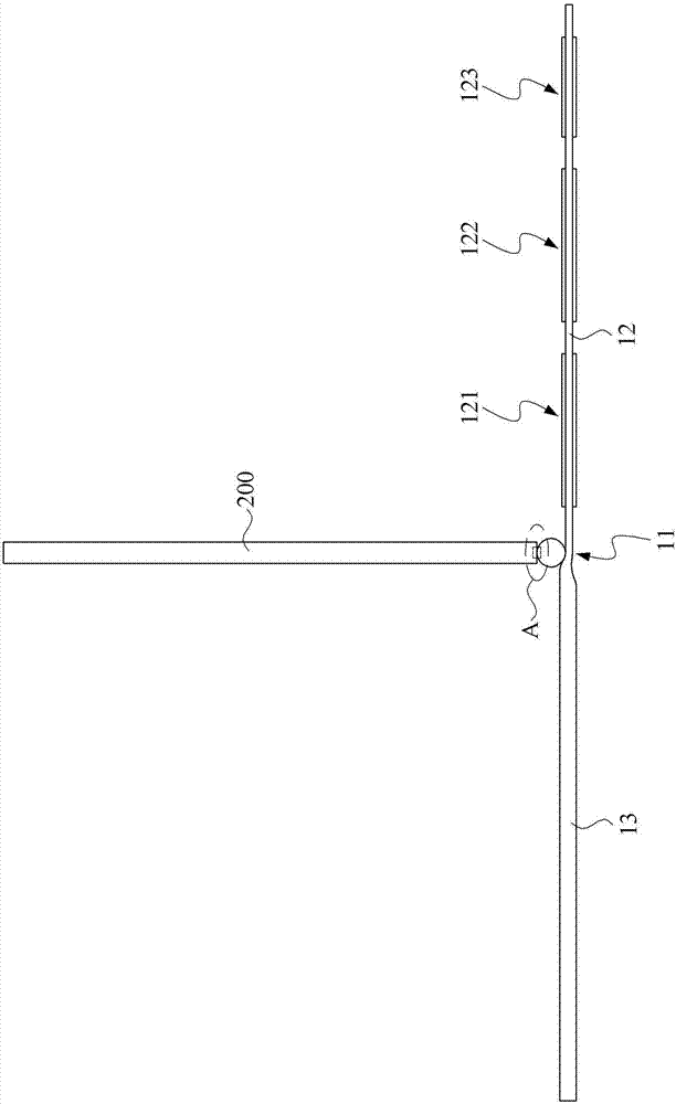
[0020] see figure 1 , Figure 2A and Figure 2B , figure 1 is an exploded perspective view showing the combination of the cover assembly and the first electronic device in the first preferred embodiment of the present invention; Figure 2A is a schematic plan view showing that the cover assembly magnetically attaches the first electronic device through the pivot portion in the first preferred embodiment of the present invention; Figure 2B for Figure 2A Circle A shows a magnified schem...


PUM


Abstract

A cover adapted to a first electronic device is provided. The first electronic device includes a first electrical connector. The cover comprises: a connecting portion; a covering portion extending from the connecting portion to cover the first electronic device; and a pivot portion. The pivot portion includes a fixing pivot member fixed to the connecting portion; and a magnetic pivot member pivotally connected to the fixing pivot member and including a second electrical connector. The second electrical connector is electrically connected to the first electrical connector when the first electronic device is connected to the magnetic pivot member.

Description

technical field [0001] The invention relates to a cover assembly, in particular to a cover assembly of an electronic device. Background technique [0002] More and more people use smart electronic devices in their work. Since most of the work needs to rely on the keyboard for text input, users usually use Bluetooth keyboards and other devices to wirelessly connect smart electronic devices, or use a keyboard device with a snap-in structure to set up smart electronic devices for wired connections , but whether it is a Bluetooth keyboard or a keyboard device with a snap-in structure, there are disadvantages. [0003] Taking the Bluetooth keyboard as an example, when the user wants to use the Bluetooth keyboard, he must first turn on the Bluetooth function of the smart electronic device to perform Bluetooth pairing and connection, and cannot input through the Bluetooth keyboard in real time. [0004] In the case of a keyboard device with a snap-in structure, although the smart...

Claims


Application Information

Patent Timeline
Patent Type & Authority Applications(China)
IPC IPC(8): G06F1/16
CPCG06F1/1615G06F1/1616G06F1/166G06F1/1669
Inventor 李青雷勇丰李冠霈李君伦许健廷
Owner ASUSTEK COMPUTER INC
Learn More