
Projection system

A projection system and projection light technology, applied in the field of projection systems, can solve problems such as ineffective use of light, ineffective use of light, loss, etc.

Active Publication Date: 2017-12-08
APPOTRONICS CORP LTD
View PDF4 Cites 9 Cited by
  • Summary
  • Abstract
  • Description
  • Claims
  • Application Information

AI Technical Summary

Problems solved by technology

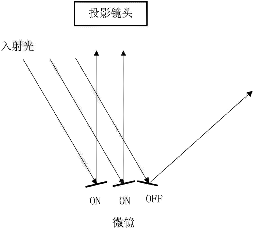
[0005] During the image modulation process, the micromirror of the DMD chip in the ON state reflects the incident light to the projection lens to form projection light, and the DMD chip will also lose a considerable amount of light by the reflection of the micromirror in the OFF state, except for the projection light The light is not being used efficiently
[0006] The problem that light other than the above-mentioned projection light is not effectively used not only exists in the scene where the spatial light modulator is a digital micromirror device, but also has the same problem in projection systems using other spatial light modulators

Method used


Image

  • Projection system
  • Projection system
  • Projection system

Examples


Embodiment Construction

[0069] The following will clearly and completely describe the technical solutions in the embodiments of the present invention with reference to the accompanying drawings in the embodiments of the present invention. Obviously, the described embodiments are only part of the embodiments of the present invention, not all of them. The technical solutions of the various embodiments of the present invention can be combined with each other on the premise of not contradicting each other, and on the basis of the realization of those skilled in the art, the combination of technical features of different embodiments can be extracted on the premise of no creative work The resulting technical solutions also belong to the protection scope of the present invention. Based on the embodiments of the present invention, other embodiments obtained by persons of ordinary skill in the art through simple deformation and the like without creative work, all belong to the scope of protection of the presen...


PUM


Abstract

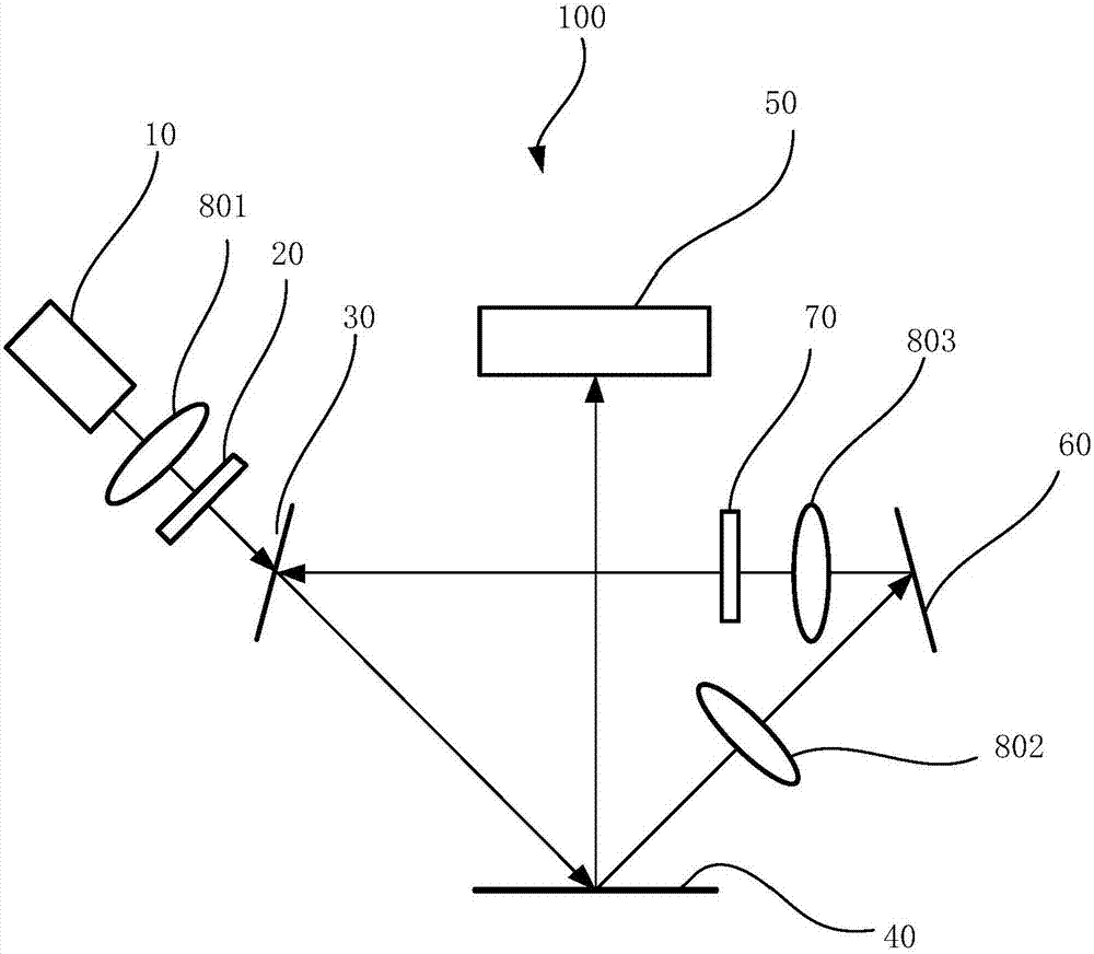
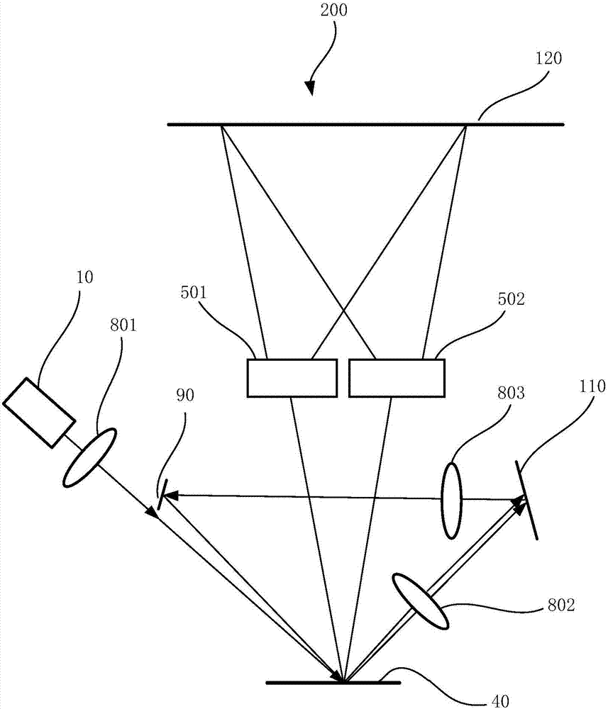
The invention provides a projection system. The projection system comprises a light source, a space light modulator, a light recycle system and a lens assembly, wherein the light source is used for emitting light of the light source and irradiating to the space light modulator, the space light modulator is used for modulating light irradiating on the space light modulator according to an image signal to form projection light and light outside the projection light, the light recycle system is used for receiving at least one part of the light outside the projection light and guiding the at least one part of the light outside the projection light to the space light modulator, and the lens assembly is used for receiving and emitting the projection light to form a projection image. By the projection system, the light outside the projection light can be effectively utilized.

Description

technical field [0001] The present invention relates to the field of projection technology, in particular to a projection system. Background technique [0002] DLP (Digital Light Processing, digital light processing) projection technology is more and more widely used due to its advantages such as high contrast, long device life, and high fill factor. In DLP projection technology, the timing of the light source output R (red), G (green), B (blue) three-color light (or, R (red), G (green), B (blue), W (white) and more The light of various colors is projected on the DMD (Digital Micromirror Device, digital micromirror device) chip, and the DMD chip reflects the light of different colors to the projection screen to form an image after receiving the control signal of the DLP control system. [0003] The DMD chip consists of hundreds of thousands or even millions of micromirrors, and one micromirror corresponds to one pixel. There is a rotating device under each micromirror. Und...

Claims


Application Information

Patent Timeline
Patent Type & Authority Applications(China)
IPC IPC(8): G03B21/14G03B21/00
CPCG03B21/008G03B21/142G03B21/2066G03B21/2073G03B21/2053G03B21/26H04N9/3182H04N9/3111G03B21/00G03B21/28H04N9/312H04N9/3167
Inventor 李屹胡飞郭祖强
Owner APPOTRONICS CORP LTD
Learn More