
Diesel engine system and control method

A technology of diesel engine and control method, which is applied in the direction of combustion engine, machine/engine, mechanical equipment, etc., can solve the problem of limited diesel mixing effect, and achieve the effects of easy design and implementation, increased fuel injection pressure, and low cost

Active Publication Date: 2020-04-10
GREAT WALL MOTOR CO LTD
View PDF6 Cites 0 Cited by
  • Summary
  • Abstract
  • Description
  • Claims
  • Application Information

AI Technical Summary

Problems solved by technology

Because of reverse flow injection, fuel atomization is better, and the center temperature of the vortex combustion chamber is higher, so setting the pre-combustion chamber is helpful to the cold start of the diesel engine, but this method has a limited effect on the improvement of the diesel mixing effect

Method used


Image

  • Diesel engine system and control method
  • Diesel engine system and control method
  • Diesel engine system and control method

Examples


Embodiment 1

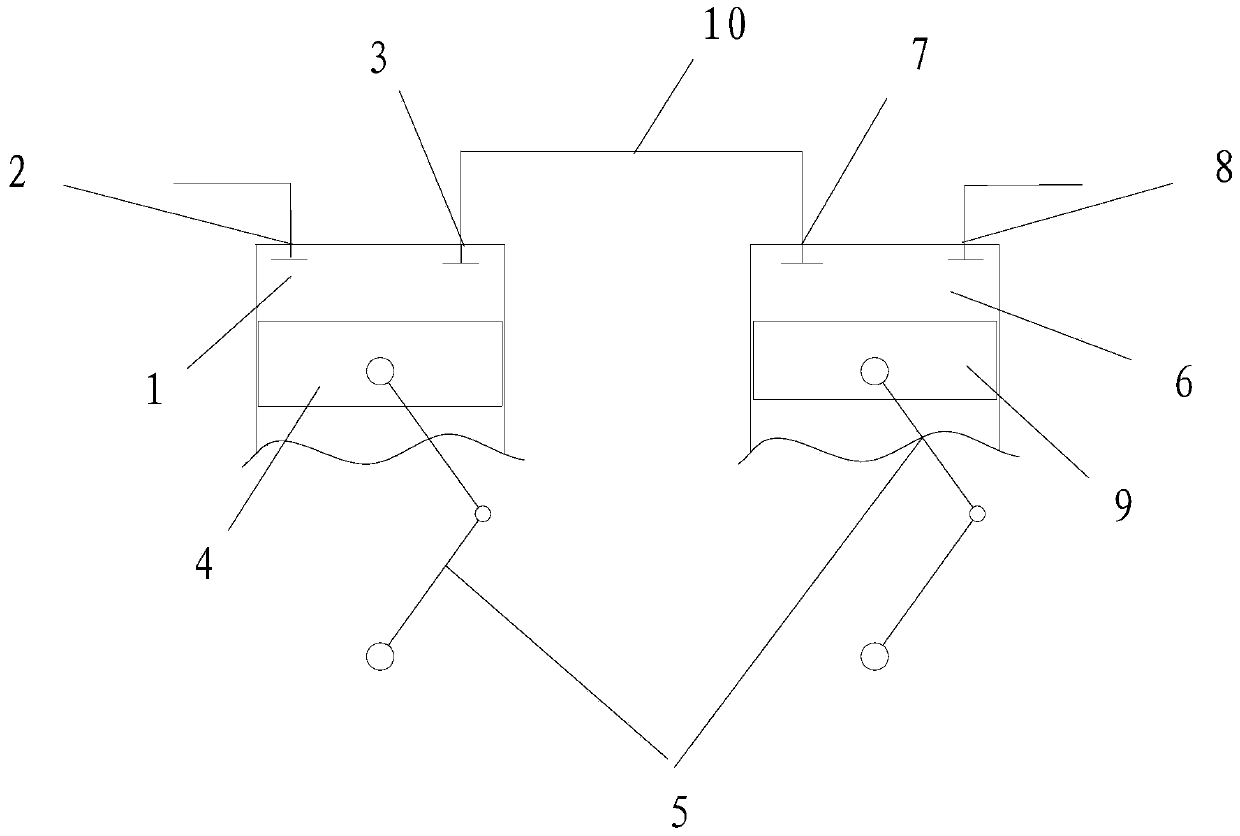
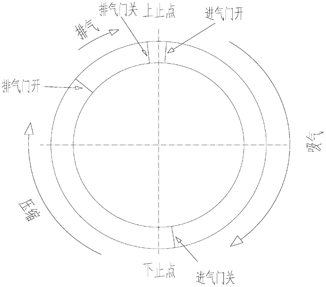
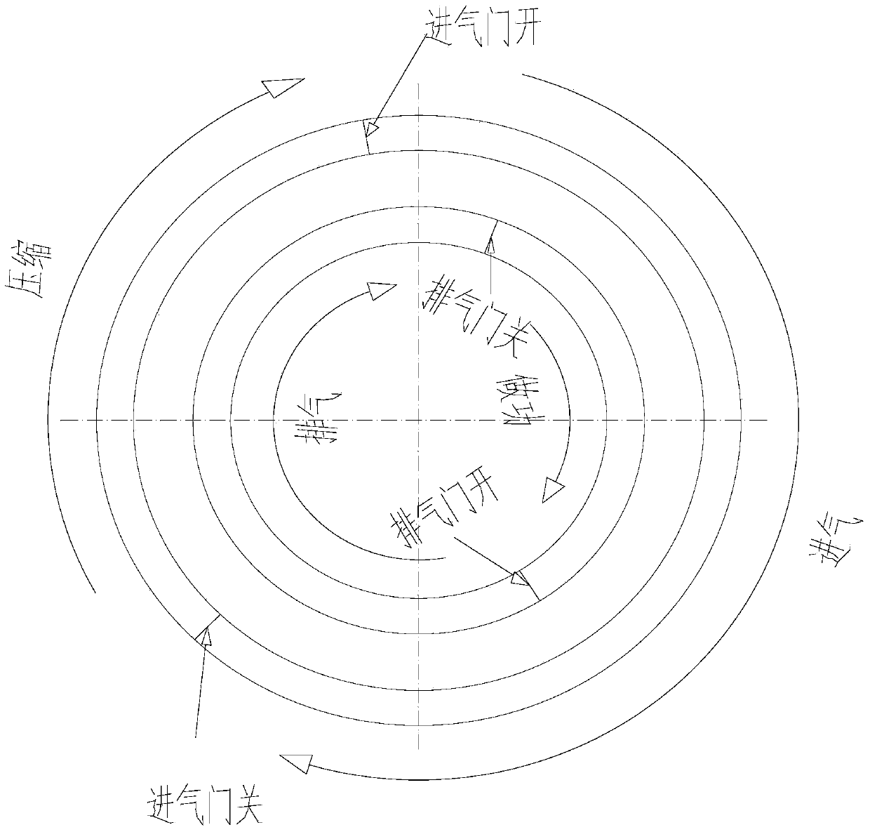
[0040] The invention relates to an air intake treatment device of a diesel engine, which is arranged upstream of the intake air of the diesel engine to form air supply to the diesel engine. The cylinder block of the oil injector is formed with a first air intake port and a first exhaust port communicated with the air intake port of the diesel engine on the cylinder block. The air intake treatment device also includes a compression device cooperating with the cylinder body, and the compression device is configured when the first air intake port on the cylinder body is opened and the first exhaust port is closed, and the fuel injector sprays oil into the cavity. , sucking air into the cavity, so that the air and fuel form a fuel-air mixture; and when the first air inlet is closed and the first exhaust port is opened, the compression device compresses the fuel-air mixture in the cavity, And before the fuel-air mixture is compressed and ignited, it is delivered from the first exha...

Embodiment 2

[0050] This embodiment relates to a diesel engine system, in which the intake air treatment device of the diesel engine as described in Embodiment 1 is arranged upstream of the intake air of the engine. Specifically, in this embodiment such as Figure 4 As shown in , the premixing cylinder 1 supplies air to two working cylinder bodies, and for the convenience of description, the two working cylinder bodies are respectively called the first working cylinder 61 and the second working cylinder 62 . The volume of the premixing cylinder 1 is greater than the volumes of the first working cylinder 61 and the second working cylinder 62 .

[0051] In this embodiment, two first air inlets and two first exhaust ports are arranged on the premixing cylinder 1. Similarly, two first working cylinders are also respectively provided with two first working cylinders on the first working cylinder 61. port and two exhaust ports of the first working cylinder, two second working cylinder air inlet...


PUM


Abstract

The invention discloses an air intake treatment device of a diesel engine, a diesel engine system and a control method. The air intake treatment device of the diesel engine is arranged at the air intake upstream of the diesel engine to feed air for the diesel engine and comprises a cylinder body and a compression device matched with the cylinder body, wherein a cavity is formed in the cylinder body; the cylinder body is provided with an oil sprayer for spraying oil into the cavity; and a first air inlet and a first air discharging hoe communicating with the air inlet of the diesel engine are formed in the cylinder body. According to the air intake treatment device of the diesel engine, the cylinder body is arranged at the air intake upstream of the diesel engine, air is fed in and diesel oil is sprayed in the cylinder body, air and diesel oil are compressed by the compression device, are then fed in the air inlet of the engine and are premixed in the cylinder body to increase the mixing angle of diesel oil; and in addition, compression of the compression device enables the diesel oil mixing gas to have certain temperature, so that the diesel oil and the air are fully mixed to improve the mixing effect of diesel oil.

Description

technical field [0001] The invention relates to the technical field of diesel engine air intake control, in particular to an intake air processing device for a diesel engine. The present invention also relates to a diesel engine system provided with the intake air processing device of the diesel engine, and a control method of the diesel engine system. Background technique [0002] Diesel engine is a kind of compression ignition engine, which is more and more favored by automobile manufacturers due to its low fuel consumption. Insufficient cold startability of the engine. At the same time, due to the low volatility of diesel, diesel engines are prone to produce black smoke when accelerating, which will also cause emissions not to meet the national standard and pollute the environment. The above-mentioned problems of diesel engines are mainly caused by the poor atomization effect of diesel oil, which makes it difficult to form a uniformly atomized fuel mixture. [0003] Th...

Claims


Application Information

Patent Timeline
Patent Type & Authority Patents(China)
IPC IPC(8): F02B1/00
CPCF02B1/00
Inventor 孙硕乔建虎张凡石磊孙俭
Owner GREAT WALL MOTOR CO LTD
Learn More