Numerical control hydraulic push-bending pipe bending machine and rebound compensation method thereof

A bending and hydraulic technology, applied in complex mathematical operations and other directions, can solve the problems of pipe stumbling, reduced bending force, small bending force, etc., and achieve reduced guide length, increased bending strength, and bending efficiency. added effect

Active Publication Date: 2017-12-08
WUHAN HUAYE AUTOMATION MACHINERY
View PDF6 Cites 1 Cited by
  • Summary
  • Abstract
  • Description
  • Claims
  • Application Information

AI Technical Summary

Problems solved by technology

However, its fixtures and accessories are complicated, the equipment is bulky, the cost is high, and the bending force is small, and it is troublesome to replace the mold. In addition, the bending mold of this form of pipe bending machine cannot use reverse deformation to control the quality of the bent pipe section, otherwise the pipe will fall into the bending mold. Not easy to release the mold
[0004] 2. Top bending machine, only manual on the market
[0007] 1. When the existing oil cylinder drives the S-shaped slider to slide, it will generate a strong force on the slider, and the bending die will generate a strong reaction force on the S-shaped slider during the sliding process, so that the existing After long-term use of the top-bending pipe bender, the above-mentioned force will generate torque on the sliding part of the S-type slider and the oil cylinder, and the above-mentioned reaction force will generate torque on the part of the S-type slider that cooperates with the bending die. These two torques cause the S-type slider to generate greater friction when sliding, resulting in a decrease in the bending force, and reduce the strength ratio of the sliding part of the S-type slider that cooperates with the bending die and the oil cylinder, resulting in the bending of the S-type slider out of shape
[0008] 2. The upper end of the slider of the existing top bending pipe bender is equipped with a bending die, and the lower end is equipped with an oil cylinder. The superposition of the devices increases the volume of the equipment
The material shape, material and heat treatment state are different, and the amount of rebound is also different. The existing top bending machine cannot effectively compensate for the rebound of the bent pipe. It can only be estimated or estimated by a similar linear slope intercept. Limited, and any kind of forming angle needs multiple tests to get the result

Method used


Image

  • Numerical control hydraulic push-bending pipe bending machine and rebound compensation method thereof
  • Numerical control hydraulic push-bending pipe bending machine and rebound compensation method thereof
  • Numerical control hydraulic push-bending pipe bending machine and rebound compensation method thereof

Examples


Embodiment Construction

[0043] The implementation of the present invention will be described in detail below in conjunction with the accompanying drawings, but they do not constitute a limitation to the present invention, and are only examples. At the same time, the advantages of the present invention are clearer and easier to understand through the description.

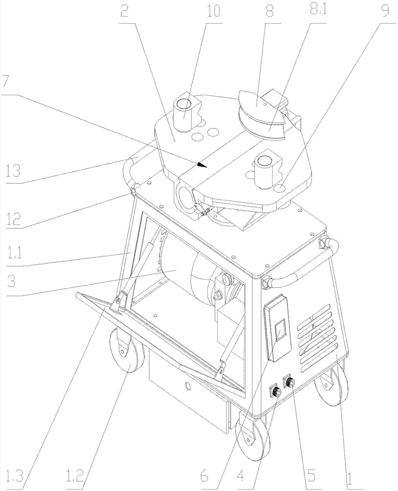
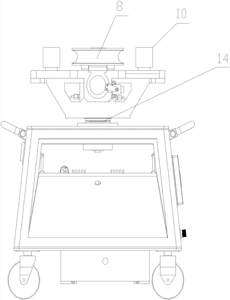
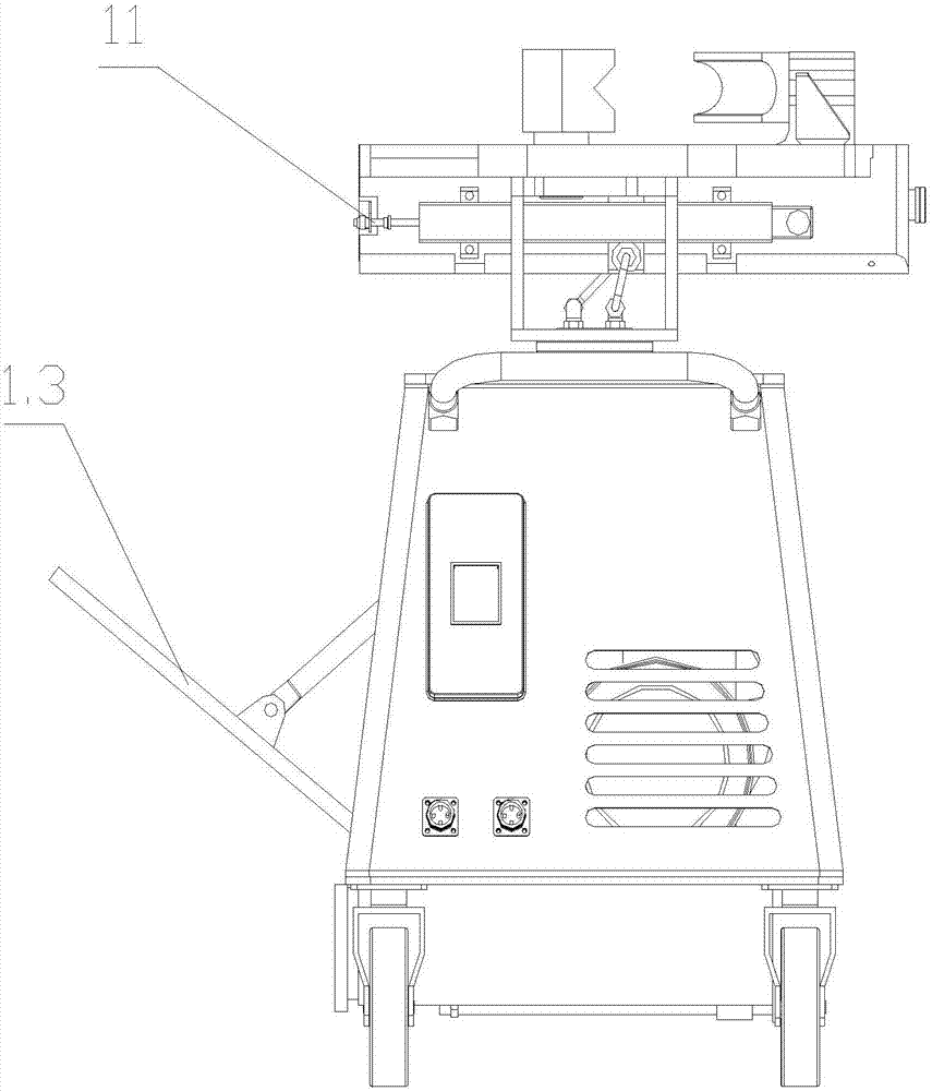
[0044] Referring to the accompanying drawings, it can be seen that a numerically controlled hydraulic top bending pipe bender includes a bending die 8 installed above the operation panel 2, and a bending die installed in the middle of the operation panel 2 that can drive the bending die 8 to move back and forth on the operation panel 2 The driving mechanism 7 is characterized in that: the bending die driving mechanism 7 includes a guide groove 21 located in the middle of the operation panel 2, and a cylinder 22 located inside the guide groove 21 and capable of sliding in the guide groove 21, the bending die 8 It is connected with one end of...


PUM


Abstract

The invention discloses a numerical control hydraulic push-bending pipe bending machine, and relates to the structure of a pipe bending machine. The pipe bending machine comprises a bending mold and a bending mold driving mechanism; the bending mold driving mechanism comprises a guide groove and a cylinder body; the bending mold is connected to the end part of one end of the cylinder body; a piston cavity is formed in the side, close to the bending mold, of the cylinder body; a piston rod is arranged in the piston cavity; a check block which is fixedly connected to the end part of the free end of the piston rod and plugs a cavity opening of the piston cavity is arranged at the cavity opening of the piston cavity; two oil ducts which are arranged at intervals and penetrate through the check block are arranged in the piston rod; a sealing block is arranged on the piston rod in a sleeving mode; a sealing gasket is arranged between the sealing block and the piston cavity; a sensor placement groove is formed in the side, away from the bending mold, of the cylinder body; a displacement sensor is arranged in the sensor placement groove; and the check block and an operation panel are of an integrated structure. According to the pipe bending machine, the working efficiency can be improved, and the occupied area can be decreased. The invention further relates to a rebound compensation method of the numerical control hydraulic push-bending pipe bending machine.

Description

technical field [0001] The invention relates to a structure of a pipe bending machine, in particular to a numerical control hydraulic top bending pipe bending machine. The invention also relates to a rebound compensation method of the digitally controlled hydraulic top-bending pipe bender. Background technique [0002] At present, there are mainly two types of pipe bending equipment: rotary bender and top bender: [0003] 1. Most of the rotary bending machines are numerically controlled in the market. It is obtained by rotating the bending pipe on the bending die. It directly detects the rotation angle of the bending die, and an angle sensor can realize the angle monitoring. However, its fixtures and accessories are complex, the equipment is bulky, the cost is high, and the bending force is small, and it is troublesome to replace the mold. In addition, the bending mold of this type of pipe bending machine cannot use reverse deformation to control the quality of the bending ...

Claims


Application Information

Patent Timeline
Patent Type & Authority Applications(China)
IPC IPC(8): B21D7/14B21D7/16G06F17/15
CPCG06F17/15B21D7/14B21D7/16Y02P70/10
Inventor 兰年山王志祥
Owner WUHAN HUAYE AUTOMATION MACHINERY
Why Eureka
Try Eureka