Usage method for stirring device of slurry at bottom of desulfurization tower in thermal power plant

The technology of a slurry stirring device and a desulfurization tower is applied in mixers with a rotating stirring device, accessories of the mixer, chemical instruments and methods, etc., and can solve the problems of increasing the failure rate of the stirring device, polluting the environment, and accelerating the use and loss of the stirring device. Achieve smooth operation, reduce damage and avoid hard collisions

Inactive Publication Date: 2017-12-05
绵阳行之智汇知识产权服务有限公司
View PDF2 Cites 1 Cited by
  • Summary
  • Abstract
  • Description
  • Claims
  • Application Information

AI Technical Summary

Problems solved by technology

However, after coal combustion in the boiler, a large amount of flue gas will be produced. The flue gas contains a large amount of harmful substances, and the direct release will seriously pollute the environment. The traditional flue gas purification treatment usually uses a desulfurization tower to desulfurize the flue gas. treatment to reduce the release of harmful substances, but the slurry at the bottom of the existing desulfurization tower contains a large number of solid particles, mainly fly ash and desulfurization medium particles, the particle size is generally 0-400µ; m, more than 90% are 20-60µ m, the concentration is 5%~28% (mass ratio), these solid particles (especially Al2O3, SiO2 particles) have very strong abrasiveness, and when the slurry at the bottom of the desulfurization tower is stirred, conventional stirring blades It is easy to be impacted by the solid phase in the slurry, causing the stirring blade to swing radially, and the resulting stress will be transmitted to the final power output end through the torque, which will increase the failure rate of the stirring device and accelerate the wear and tear of the stirring device.

Method used


Image

  • Usage method for stirring device of slurry at bottom of desulfurization tower in thermal power plant

Examples


Embodiment 1

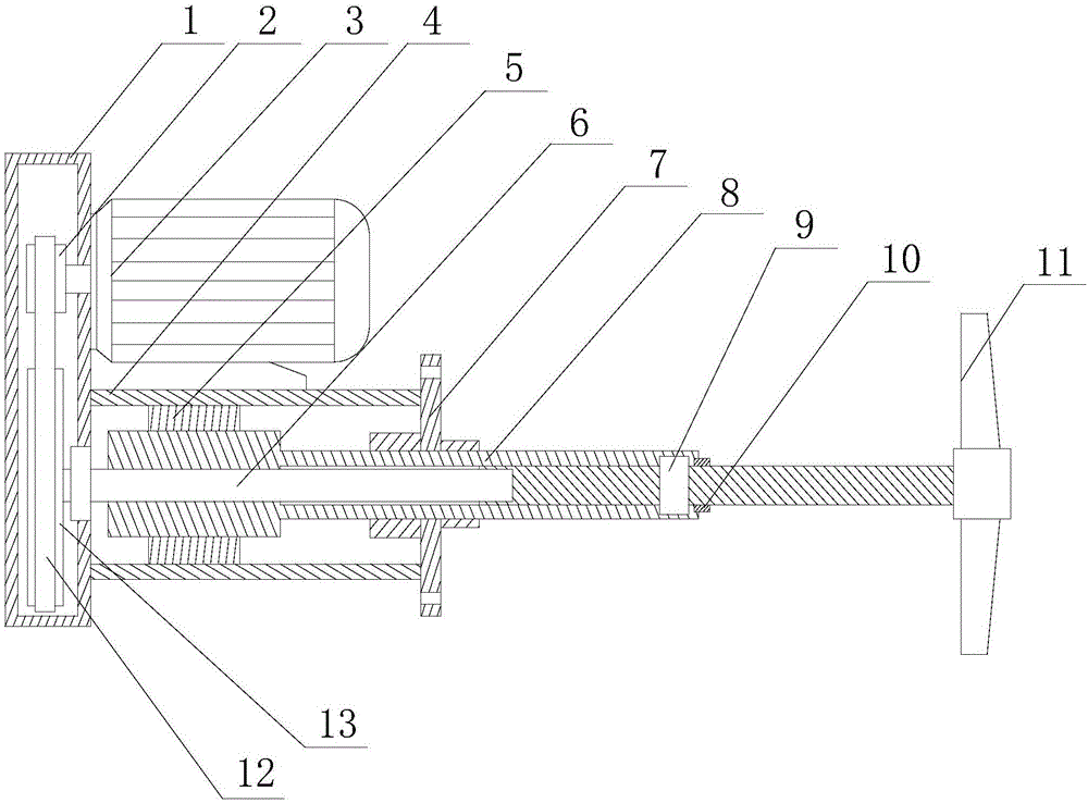
[0021] Such as figure 1 As shown, this embodiment includes the following steps: first, fix the fixing cylinder on the desulfurization tower through the flange, so that the blades are placed in the desulfurization tower, start the motor, and through the linkage between the driving wheel, the belt and the driven wheel, the linkage The shaft starts to rotate, and when it rotates, most of the linkage shaft is covered by the sleeve, and an annular groove is opened on the inner peripheral wall at the end of the extension section of the sleeve, and the follower ring on the linkage shaft matches the annular groove; the motor 3 It is arranged on the fixed cylinder 4, and the output end of the motor 3 passes through the side wall of the box body 1 and then continues to extend. The driving wheel 2 is installed on the extension section of the output end of the motor 3, and the end of the fixed cylinder 4 is far away from the box body 1 The end is equipped with a flange 7, and also include...


PUM


Abstract

The invention discloses a usage method for a stirring device of slurry at the bottom of a desulfurization tower in a thermal power plant. The method comprises the following steps: a fixed cylinder is fixed to the desulfurization tower through a flange plate, blades are placed in the desulfurization tower, an electrical machine is started, a universal driving shaft starts to rotate through linkage of a driving wheel, a belt and a driven wheel, when the universal driving shaft is rotated, a sleeve sleeves most of the universal driving shaft, annular grooves are arranged in the inner circumferential wall of the tail end of the extended segment of the sleeve, and follow-up rings of the universal driving shaft are matched with the annular grooves. According to the invention, in order to solve a problem in the prior art that when the slurry at the bottom of the desulfurization tower is stirred, stirring blades are badly damaged, a stirring and mixing working procedure applicable to slurry with relatively large solid-phase particles is designed, and stirring efficiency of the slurry is improved under the premise that the stirring blades work stably.

Description

technical field [0001] The invention relates to the field of thermal electric field power generation, in particular to a method for using a slurry stirring device at the bottom of a desulfurization tower of a thermal power plant. Background technique [0002] The thermal power plant uses coal as fuel, and the coal is burned in the boiler to heat the water in the boiler to generate steam, and then the steam with a certain temperature and pressure from the boiler enters the steam turbine through the main steam valve and the regulating steam valve, and flows through the steam turbine in turn. A series of ring-mounted nozzle cascades and moving blade cascades expand and do work, convert their heat energy into mechanical energy that drives the turbine rotor to rotate, and drive the generator to generate electricity through the coupling. The steam after expansion and work is discharged from the steam exhaust part of the steam turbine. When the condenser is condensed into water, it...

Claims


Application Information

Patent Timeline
Patent Type & Authority Applications(China)
IPC IPC(8): B01F7/04B01F15/00
CPCB01F27/2121B01F27/70B01F2035/353B01F2035/351B01F35/322B01F35/31
Inventor 王伟
Owner 绵阳行之智汇知识产权服务有限公司
Why Eureka
Try Eureka