Reluctance motor, and method for manufacturing rotor core used in reluctance motor
A reluctance motor and a manufacturing method technology, which are applied in the directions of magnetic circuit rotating parts, magnetic circuit shape/style/structure, etc., can solve the problem of large torque pulsation of reluctance motor, and achieve the effect of reducing torque pulsation
- Summary
- Abstract
- Description
- Claims
- Application Information
AI Technical Summary
Problems solved by technology
Method used
Image
Examples
Embodiment approach 1
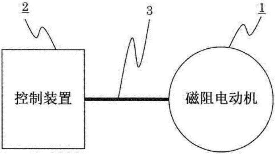
[0049] figure 1 It is a figure which shows the system at the time of using the reluctance motor which concerns on Embodiment 1 of this invention. exist figure 1 Among them, a reluctance motor 1 is connected to a control device 2 via a power supply line 3 . Furthermore, the reluctance motor 1 is a motor that converts electric energy supplied from the control device 2 into mechanical energy.
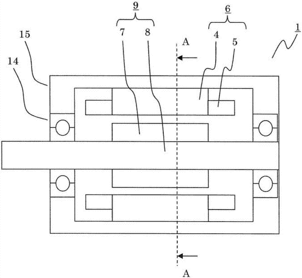
[0050] figure 2 It is a cross-sectional view of the reluctance motor 1 in Embodiment 1 of the present invention cut along the axial direction. exist figure 2 Among them, the stator 6 and the rotor 9 are configured to freely rotate with each other through a mechanical gap using bearings 14 , and the stator 6 and the rotor 9 are inserted into the frame 15 by press-fitting or shrink-fitting, and are fixed.
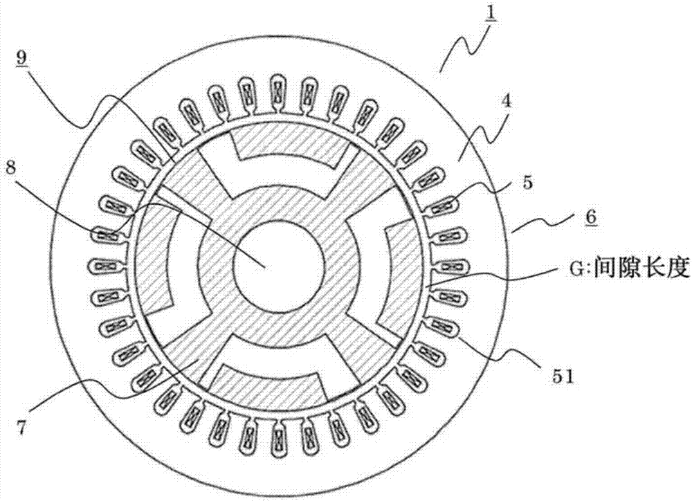
[0051] The stator 6 is configured by providing a winding 5 to a stator core 4 made of an iron core. Furthermore, the stator 6 has a function of generating a rotating magnetic fiel...
Embodiment approach 2
[0164] Figure 15 It is a sectional view of the rotor core 7 of the reluctance motor 1 according to Embodiment 2 of the present invention. This structure is similar to the previous Figure 11 Very similar, but different in that the relative angle ξ of the right slit wall 111k of the first slit end 113k of the first group to the right slit wall 111m of the first slit end 113m of the second group 1 2 , the relative angle ψ between the left slit wall 112l of the second slit end 113l of the first group and the left slit wall 112m of the first slit end 113m of the second group 1 2 It is set by the following formulas (7) and (8).
[0165] 【Equation 7】
[0166]
[0167]
[0168] In the above formulas (7) and (8), each symbol represents the following content, respectively.
[0169] ·g is the number of groups, in Figure 15 Among them, g=2.
[0170] ·Set the interval between the first group and the jth group as ξ 1 j and ψ 1 j , so here, j=2.
[0171] k i and s j S...
Embodiment approach 3
[0180] Figure 16 It is a sectional view of the rotor core 7 of the reluctance motor 1 according to Embodiment 3 of the present invention. This structure is similar to the previous Figure 11 Very similar, but make Group 1 consist of slit ends 113o and 113r and Group 2 consist of slit ends 113p and 113q. And, by setting n in each group i = l i, so that the shape of the slit 11 is line-symmetric with respect to the circumferential center of the slit 11, which is the same as Figure 11 different.
[0181] Even with the configuration as described above, the qNs / p-order component of the torque ripple can be reduced, and an effect can be obtained in which the characteristic can be made the same when the torque is output to the left and when the torque is output to the right. If these are summed up, then Figure 16 Angle δ in 1 2 ,δ 2 2 , ε 1 2 , ε 2 2 become as shown in Table 4.
[0182] [Table 4]
[0183] Table 4. Figure 12 angle in
[0184]
PUM
 Abstract
Description
Claims
Application Information
 - Generate Ideas
- Intellectual Property
- Life Sciences
- Materials
- Tech Scout
- Unparalleled Data Quality
- Higher Quality Content
- 60% Fewer Hallucinations
Browse by: Latest US Patents, China's latest patents, Technical Efficacy Thesaurus, Application Domain, Technology Topic, Popular Technical Reports.
© 2025 PatSnap. All rights reserved.Legal|Privacy policy|Modern Slavery Act Transparency Statement|Sitemap|About US| Contact US: help@patsnap.com


