Eureka AIR delivers breakthrough ideas for toughest innovation challenges, trusted by R&D personnel around the world.

Permanent-magnetic rotor structure of motor of shielding pump

A permanent magnet rotor, shielded pump technology, applied in the shape/style/structure of the magnetic circuit, the rotating parts of the magnetic circuit, the magnetic circuit and other directions, can solve the problems affecting the performance of the motor, the limited improvement space, and the increase of the temperature of the motor, etc. Improve efficiency, improve motor performance, and reduce the effect of motor temperature rise

Inactive Publication Date: 2018-09-25
大连帝国屏蔽电泵有限公司
View PDF4 Cites 0 Cited by
  • Summary
  • Abstract
  • Description
  • Claims
  • Application Information

AI Technical Summary

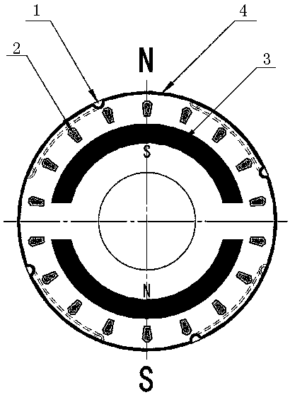
Problems solved by technology

[0002] At present, the canned electric pumps used in domestic chemical plants all use three-phase asynchronous motors as supporting canned motors. For normal three-phase asynchronous canned motors, the rotors mostly use squirrel-cage cast aluminum rotors or copper bar rotors. Due to the rotating magnetic field of asynchronous motors and The existence of rotor slip will cause eddy current loss on the stator shielding sleeve, and the shielded pump produced by the three-phase asynchronous motor will generate eddy current loss in the shielding sleeve during operation, which will reduce the motor by 15%~20%. Efficiency, there is limited room for improvement in terms of product efficiency and power saving
[0003] In addition, due to the heating of the stator shield sleeve of the three-phase asynchronous shielded motor, the temperature rise of the motor will be increased, which will affect the performance of the motor.

Method used


Image

  • Permanent-magnetic rotor structure of motor of shielding pump
  • Permanent-magnetic rotor structure of motor of shielding pump

Examples


Embodiment Construction

[0011] The structure of the permanent magnet rotor of the canned pump motor of the present invention is as follows: figure 1 and figure 2 As shown, it includes arc-shaped magnetic steel 3, cast aluminum winding 2 and shielding sleeve 4, the rotor is embedded with arc-shaped magnetic steel 3, the rotor is provided with cast aluminum winding 2, the outer side of the rotor is provided with shielding sleeve 4, and the stainless steel shielding sleeve 4 is on the A diversion groove 1 is provided.

[0012] The invention adopts the matching structure of the permanent magnet synchronous motor and the pump, designs a self-starting permanent magnet synchronous shielded electric pump, designs a self-starting cast aluminum winding 2 on the rotor, and relies on the asynchronous torque generated by the interaction between the stator rotating magnetic field and the cage rotor to realize starting . During normal operation, the rotor runs at synchronous speed, and the cage rotor no longer f...


PUM


Abstract

A permanent-magnetic rotor structure of a motor of a shielding pump comprises arched magnetic steel, a cast aluminum winding and a shielding sleeve. The arched magnetic steel is embedded into a rotor,the rotor is provided with the cast aluminum winding, the shielding sleeve is arranged outside the rotor, and the stainless steel shielding sleeve is provided with a diversion groove. According to the permanent-magnetic rotor structure of the motor of the shielding pump, a permanent magnet synchronous motor replaces a three-phase asynchronous motor, so that the efficiency of the motor is improvedto large extent; a permanent magnet is embedded with the arched magnetic steel, so that the torque of a magnetic pole of the permanent magnet fluctuates much narrowly; and the diversion grooves are designed in the external diameter of the rotor shielding sleeve, so that the flow of a heat radiation medium between a stator and the rotor can be increased, the heat radiation condition is improved, temperature rise of the motor is reduced, and the motor performance is improved.

Description

technical field [0001] The invention relates to the technical field of shielded electric pumps, in particular to a motor matched with the shielded electric pump. Background technique [0002] At present, the canned electric pumps used in domestic chemical plants all use three-phase asynchronous motors as supporting canned motors. For normal three-phase asynchronous canned motors, the rotors mostly use squirrel-cage cast aluminum rotors or copper bar rotors. Due to the rotating magnetic field of asynchronous motors and The existence of rotor slip will cause eddy current loss on the stator shielding sleeve, and the shielded pump produced by the three-phase asynchronous motor will generate eddy current loss in the shielding sleeve during operation, which will reduce the motor by 15%~20%. Efficiency, there is limited room for improvement in terms of product efficiency and power saving. [0003] In addition, the heating of the stator shield sleeve of the three-phase asynchronous...

Claims


Application Information

Patent Timeline
Patent Type & Authority Applications(China)
IPC IPC(8): H02K1/27
CPCH02K1/272
Inventor 王本军杨敬修贺北华邢韦韦陈辉赵久洲
Owner 大连帝国屏蔽电泵有限公司
Why Eureka
Eureka Blog
Learn More