Container and packing method

A container and container body technology, applied in packaging and other directions, can solve problems such as damage and pollution of optical components

Active Publication Date: 2017-12-01
NIPPON ELECTRIC GLASS CO LTD
View PDF5 Cites 1 Cited by
  • Summary
  • Abstract
  • Description
  • Claims
  • Application Information

AI Technical Summary

Problems solved by technology

[0008] However, if the protective sheet is used in an unconstrained state as described above, the protective sheet may come into contact with the effective surface of the optical element and cause damage or contamination to the optical element depending on the degree of spacing between the optical elements.

Method used


Image

  • Container and packing method
  • Container and packing method
  • Container and packing method

Examples


Embodiment Construction

[0044] Hereinafter, modes for implementing the present invention will be described in detail with reference to the drawings.

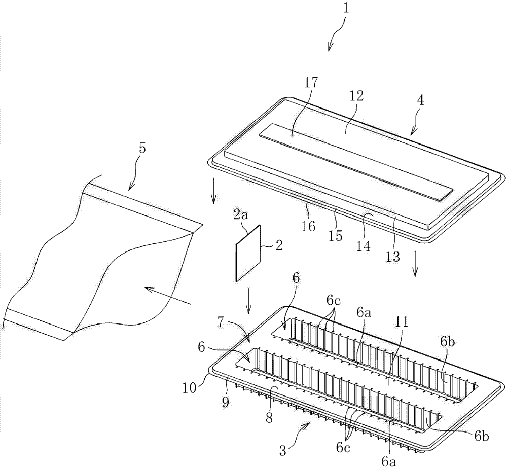
[0045] Figure 1 to Figure 8 The first embodiment of the container and packaging method according to the present invention is shown. Such as figure 1 As shown, the container 1 includes a container body 3 for accommodating an optical element 2 , a lid 4 covering the container body 3 , and a compression package 5 for compressing the container body 3 and the lid 4 . The container body 3 and the lid body 4 are made of, for example, a transparent resin material, and are formed into predetermined shapes by vacuum forming or other various forming methods.

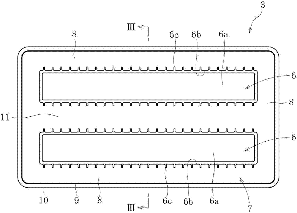
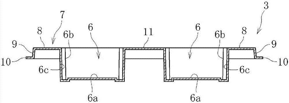
[0046] Such as Figure 1 to Figure 4 As shown, the container main body 3 includes: a housing portion 6 configured in a rectangular shape in plan view and capable of housing a plurality of optical elements 2 ; and a base portion 7 configured to surround the housing portion 6 .

[0047] The housing port...


PUM


Abstract

A container (1) is provided with: a container main body (3) for accommodating a plurality of optical elements (2); a lid body (4) for covering the container main body (3); and a compression pack (5) for compressing the container main body (3) and the lid body (4). A top plate section (12) of the lid body (4) is deformed in a convex shape while in contact with upper end sections (2a) of all of the optical elements (2) accommodated in the container main body (3) as a result of the lid body (4) and the container main body (3) being compressed by the compression pack (5) in a state in which the lid body (4) is disposed so as to cover the container main body (3), and the top plate section further presses the upper end sections (2a) of the optical elements (2) by utilizing the tension caused by such convex deformation. The container main body (3) and / or the lid body (4) of the container (1) is provided with a regulating unit for regulating the degree of the convex deformation in the top plate section (12) of the lid body (4).

Description

technical field [0001] The present invention relates to a container for accommodating optical elements including, for example, rectangular plate glass, and a method for packaging optical elements using the container. Background technique [0002] For example, a cover glass used in an image sensor of a digital camera is an optical element obtained by forming an optical filter such as an infrared cut filter on the surface of a plate glass by vacuum deposition or the like. As such an optical element, a very small rectangular optical element is used in order to be incorporated in an optical device such as a digital camera. In order to manufacture such an optical element, a method is generally employed in which an optical filter is deposited on the surface of a large plate glass, and then the plate glass is cut into small rectangles. The optical element thus obtained is packaged and stored in a predetermined container until it is assembled in an optical device, or shipped in a s...

Claims


Application Information

Patent Timeline
IPC IPC(8): B65D85/86B65D77/26
CPCB65D77/26B65D85/38B65D2585/86
Inventor 松浦建太郎
Owner NIPPON ELECTRIC GLASS CO LTD
Why Eureka
Try Eureka