
Piston for syringes and syringes

A technology for syringes and pistons, applied in the field of syringes, can solve problems such as missed hearing and weak sound signals, and achieve reliable pushing and automatic centering effects

Active Publication Date: 2017-12-01
OMSI SARL
View PDF7 Cites 4 Cited by
  • Summary
  • Abstract
  • Description
  • Claims
  • Application Information

AI Technical Summary

Problems solved by technology

Furthermore, only a very weak acoustic signal occurs in this configuration of the syringe, which is usually missed in the case of use

Method used


Image

  • Piston for syringes and syringes
  • Piston for syringes and syringes
  • Piston for syringes and syringes

Examples


Embodiment Construction

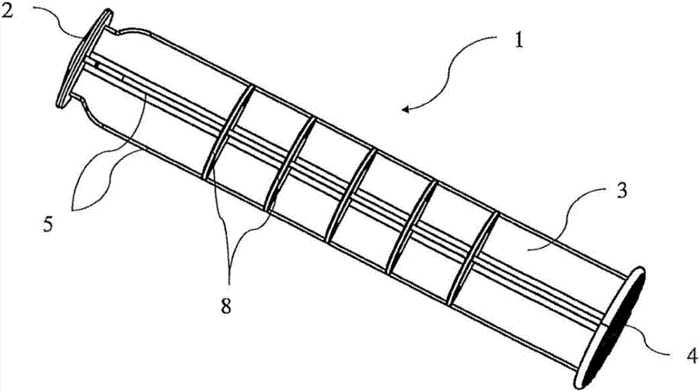
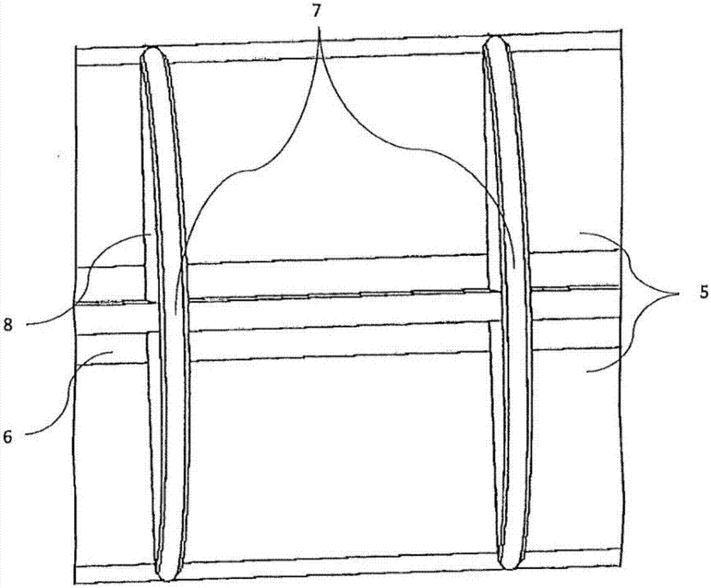
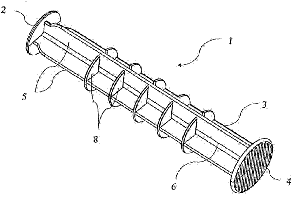
[0039] figure 1 and figure 2 A first embodiment of the piston 1 is concerned. In this case, the piston 1 has a piston rod 3 , a piston head 2 is located at one end of the piston rod, and an actuating section 4 is located at the other end of the piston rod. The piston rod 3 consists of four pairs of vertically standing axial webs 5 . These axial webs 5 lead into a common central intersection or core section 6 that accommodates the longitudinal axis. figure 2 In the enlarged view, two of the balancing rod bodies 8 arranged in parallel on the piston rod 3 and extending in the circumferential direction are shown. The balancing rod body 8 has a completely surrounding disk-like or plate-like basic shape and has a likewise completely surrounding excitation edge 7 on the radially outwardly directed edge. The radial distance of the balancing rod body 8 from the longitudinal axis 12 is greater here than the radial distance of the axial web 5 from the longitudinal axis 12 of the pi...


PUM


Abstract

In a piston for a syringe, in particular an injection syringe, which has a hollow body receiving the piston, comprising a piston head for fluid-tight delimitation of a liquid chamber of the syringe, and a piston rod firmly connected to the piston head and having an actuation portion on which the piston can be actuated for insertion into the hollow body, wherein the piston rod is formed by a plurality of axial webs which extend in the longitudinal direction and which have a radial axial extent outwards from the longitudinal axis and open radially into a common intersection portion receiving the longitudinal axis, wherein at least one free excitation edge protruding radially beyond the radial axial extent is provided on the piston rod, which excitation edge can be brought into engagement with an oscillation exciter of the hollow body upon insertion of the piston, in such a way that an acoustic signal is emitted, provision is made that an oscillation arm body arranged between two axial webs couples the excitation edge to the intersection portion in such a way that, in the event of oscillatory excitation in the axial direction, the oscillation arm body has a radial oscillation arm length, between the excitation edge and the intersection portion, of at least 40% of the radial axial extent.

Description

technical field [0001] The invention relates to a plunger for a syringe, especially a hypodermic syringe. Here, the piston is designed in such a way that it gives an audible and tactile feedback to the operator when ejecting the liquid to be injected, in order to inform the operator of the amount of liquid that has been ejected. Conventional pistons for syringes of this type comprise a piston head which serves to delimit a liquid chamber of the syringe in a fluid-tight manner, which is delimited on the outside by an in particular cylindrical hollow body. The liquid is pushed from the fluid chamber to the injection end of the syringe by means of a piston which travels in a liquid-tight manner through the hollow cylinder, where it is important to determine the precise injection volume. Background technique [0002] Visual markings on the hollow cylinder designate the different spray volumes that correspond to certain fluid volumes, thereby providing the operator with visual c...

Claims


Application Information

Patent Timeline
IPC IPC(8): A61M5/178A61M5/24A61M5/315
CPCA61M5/178A61M5/24A61M5/31511A61M5/3158A61M5/31595A61M2005/31508A61M2205/582A61M2205/581A61M5/31515A61M5/31568
Inventor 哈马德·M·奥欧玛尔
Owner OMSI SARL
Learn More