
Transformer forced water circulation cooling system and control method therefor

A technology for water circulation cooling and transformers, applied in the direction of transformer/inductor cooling, transformer/inductor components, electrical component structure associations, etc., can solve the problems of complex control logic of cooling equipment, complex structure of split cooling system, etc. Operation burden, avoid additional temperature measuring devices, and control the effect of fast response

Inactive Publication Date: 2017-12-01
SHANGHAI MUNICIPAL ELECTRIC POWER CO +2
View PDF5 Cites 8 Cited by
  • Summary
  • Abstract
  • Description
  • Claims
  • Application Information

AI Technical Summary

Problems solved by technology

The structure of the split cooling system using this cooling method is complex, generally including transformers, oil-water heat exchangers, water cooling towers, circulating water pumps, temperature detection, flow detection and other cooling equipment and auxiliary operating equipment, and the control logic of the cooling equipment is also relatively complicated

Method used


Image

  • Transformer forced water circulation cooling system and control method therefor
  • Transformer forced water circulation cooling system and control method therefor
  • Transformer forced water circulation cooling system and control method therefor

Examples


Embodiment Construction

[0044] The present invention will be further described below through specific embodiments in conjunction with the accompanying drawings. These embodiments are only used to illustrate the present invention, and are not intended to limit the protection scope of the present invention.

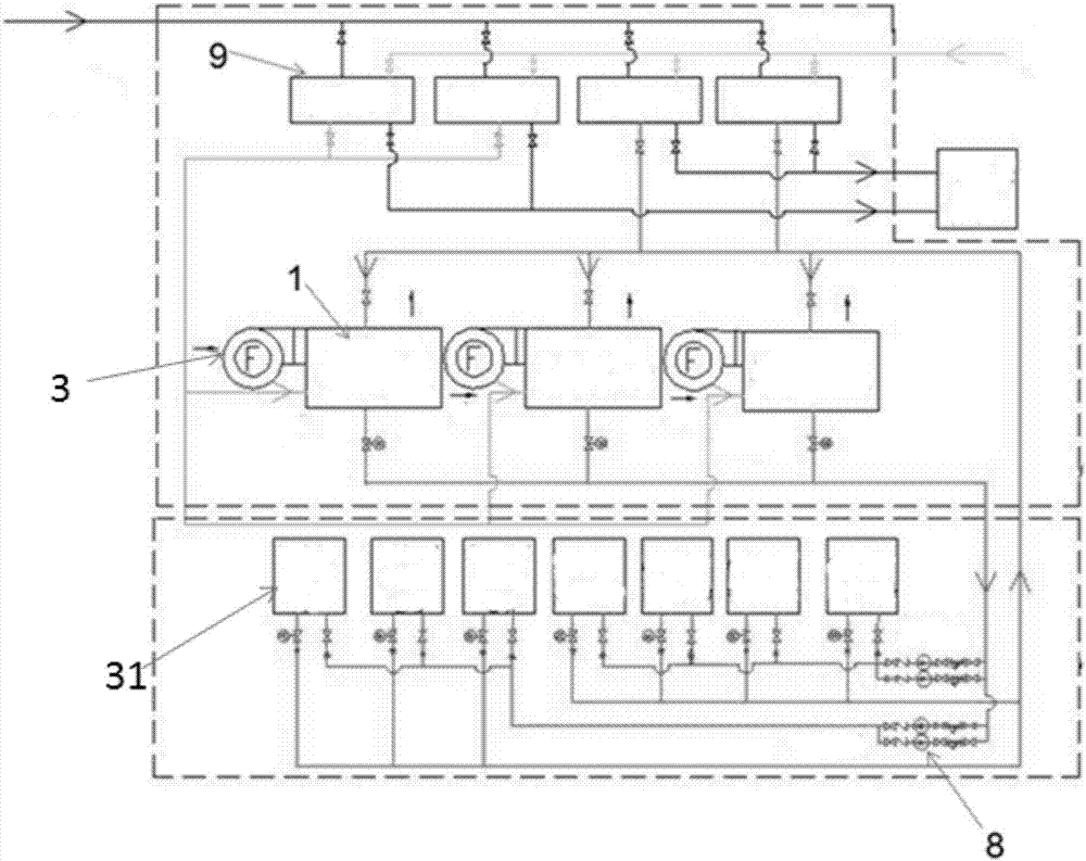
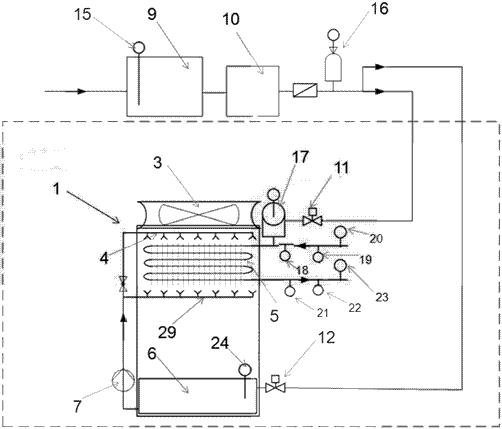
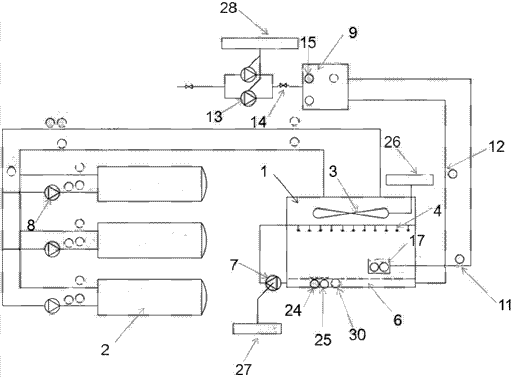
[0045] Such as figure 1 , figure 2 and image 3 As shown, the present invention provides a transformer forced water circulation cooling system, comprising:

[0046] A cooling device connected to the transformer 31, which is used to cool the oil in the oil pipe of the transformer 31 with cooling water;

[0047] A water replenishing device connected to the cooling device, which is used to supplement cooling water to the cooling device, and,

[0048] The signal detection device arranged on the cooling device, the water replenishing device and the transformer is used to detect the water temperature in the cooling device and the water replenishing device, and the oil temperature in the transformer ...


PUM

PropertyMeasurementUnit
Conductivityaaaaaaaaaa

Abstract

The invention discloses a transformer forced water circulation cooling system. The transformer forced water circulation cooling system comprises a cooling apparatus connected with the transformer and used for cooling oil in the transformer by cooling water, a water supplementing apparatus connected with the cooling apparatus and used for supplementing water for the cooling apparatus, and a signal detection apparatus arranged on the cooling apparatus, the water supplementing apparatus and the transformer and used for detecting the water temperature in the cooling apparatus and the water supplementing apparatus and the oil temperature in the transformer. By taking the temperatures indicated by an oil surface temperature indicating meter and a winding temperature indicating meter on the transformer as the basis for switching of the cooling equipment, internal temperature change of the transformer can be reflected effectively, an additional temperature measurement apparatus also can be avoided, and the hardware cost of the control system is lowered; and the control method is simple and concise in logic and a large amount of calculation in the control process is not needed, so that control response is high in speed, the control system is simple and convenient to operate, and the method is applicable to actual operation of the substation.

Description

technical field [0001] The invention relates to the technical field of transformer cooling equipment, in particular to a transformer forced water circulation cooling system and a control method thereof. Background technique [0002] With the development and expansion of cities, the characteristics of large cities with dense population, high-rise buildings, high power load density and the scarcity of land resources at the urban load center are simultaneously emerging. The construction of large-capacity substations with high-voltage levels underground has become a solution to meet the city's ever-increasing power load demand. The equipment in the underground substation is compactly arranged, and has high requirements for equipment operation reliability and noise control. If the ordinary integrated heat dissipation method is adopted, the transformer room is required to have a larger air inlet and outlet area, and strong air exhaust measures are taken to improve heat dissipatio...

Claims


Application Information

Patent Timeline
IPC IPC(8): H01F27/08H01F27/12H01F27/16H01F27/22H01F27/40
CPCH01F27/085H01F27/12H01F27/16H01F27/22H01F27/40H01F27/402H01F2027/406
Inventor 魏本刚黄华戴明秋傅正财
Owner SHANGHAI MUNICIPAL ELECTRIC POWER CO
Learn More