Heat recovery fresh air equipment

A technology of heat recovery and heat recovery core, which is applied in the field of air conditioning, can solve the problems of large unit size, unpopularity, selection of filters and heat recovery cores that cannot be too small, and reduce functional components and indoor space Small, easy interior design effect

Pending Publication Date: 2017-12-01
GREE ELECTRIC APPLIANCES INC
View PDF6 Cites 0 Cited by
  • Summary
  • Abstract
  • Description
  • Claims
  • Application Information

AI Technical Summary

Problems solved by technology

As for the heat recovery fresh air unit with two-way flow, because this type of unit needs to be equipped with two separate air ducts inside, and in order to achieve the functions of large air volume and high heat recovery, the selection of the filter and heat recovery core The volume should not be too small, which will make the unit bulky, resulting in poor applicability of the heat recovery unit, which is not very popular in the market

Method used


Image

  • Heat recovery fresh air equipment
  • Heat recovery fresh air equipment
  • Heat recovery fresh air equipment

Examples


Embodiment Construction

[0026] The technical solutions of the present invention will be described in further detail below with reference to the accompanying drawings and embodiments.

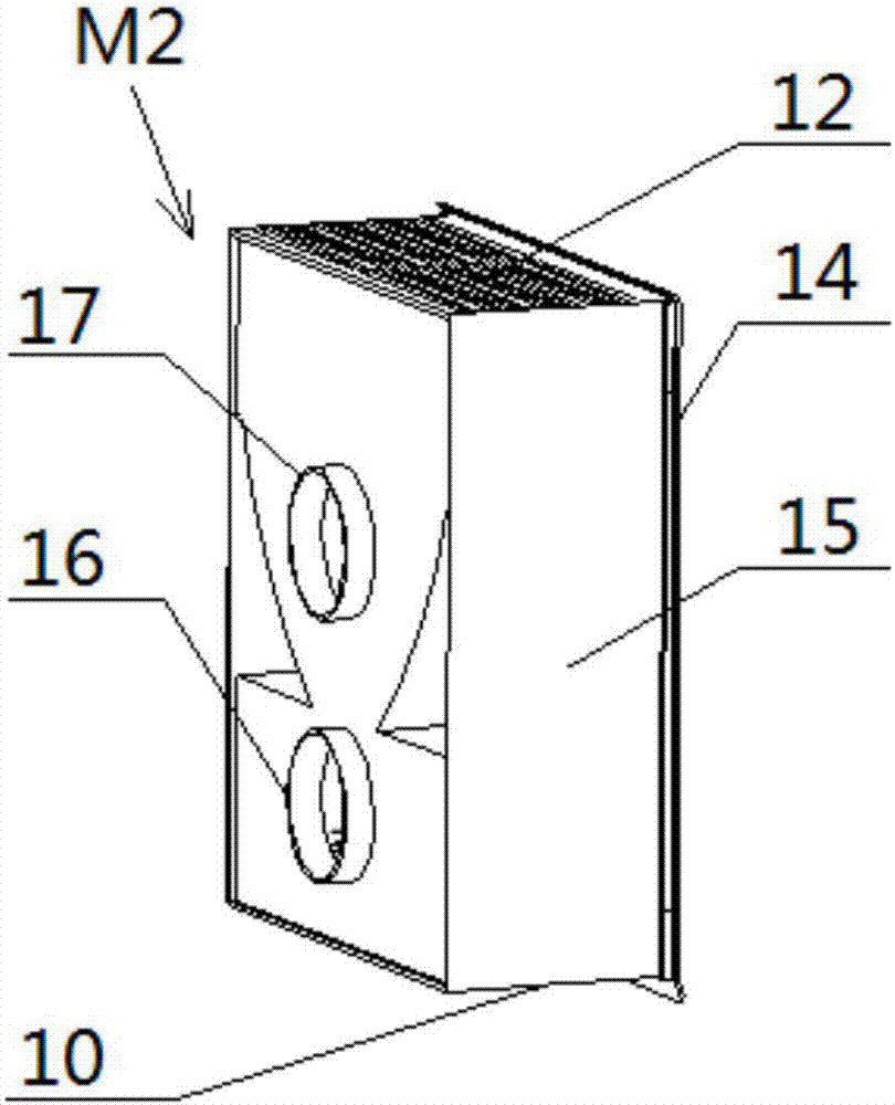
[0027] Such as figure 1 Shown is a schematic diagram of the internal structure of an embodiment of the heat recovery fresh air equipment of the present invention. In this embodiment, the heat recovery fresh air equipment includes: an indoor unit M2 , an outdoor unit M1 and a heat recovery core 2 . The indoor unit M2 includes a fresh air cavity and an exhaust air passage which are not connected inside. The outdoor unit M1 includes an exhaust cavity and a fresh air channel that are not connected inside. The fresh air cavity of the indoor unit M2 is connected to the fresh air channel of the outdoor unit M1, the exhaust channel of the indoor unit M2 is connected to the exhaust cavity of the outdoor unit M1, and the heat recovery core 2 is installed between the fresh air channel and the exhaust cavity of the outdoor unit ...


PUM


Abstract

The invention relates to heat recovery fresh air equipment which comprises an indoor unit (M2), an outdoor unit (M1) and a heat recovery core body (2), wherein the indoor unit (M2) comprises a fresh air cavity and an exhaust channel, and the insides of the fresh air cavity and the exhaust channel do not communicate with each other; the outdoor unit (M1) comprises an exhaust cavity and a fresh air channel, and the insides of the exhaust cavity and the fresh air channel do not communicate with each other; the fresh air cavity of the indoor unit (M2) communicates with the fresh air channel of the outdoor unit (M1); the exhaust channel of the indoor unit (M2) communicates with the exhaust cavity of the outdoor unit (M1); and the heat recovery core body (2) is arranged at a connection position of the fresh air channel and the exhaust cavity of the outdoor unit (M1) and is used for enabling outdoor fresh air flowing through the fresh air channel to recycle heat or cold from indoor exhausted air flowing through the exhaust cavity. The heat recovery fresh air equipment disclosed by the invention is of an indoor and outdoor unit split type structure; and the heat recovery core body is arranged in the indoor unit, and is used for recycling the heat or cold from the indoor exhausted air, so that the indoor unit occupies a smaller indoor space.

Description

technical field [0001] The invention relates to the field of air conditioning, in particular to a heat recovery fresh air device. Background technique [0002] At present, many aspects of the human living environment are increasingly being influenced by modern civilization. With the application of air-conditioning systems, the use of various synthetic building materials, the popularization of modern office equipment, the improvement of building airtightness, and the reduction of fresh air volume as much as possible for energy saving or cost reduction, indoor PM2.5 concentrations, toxic gases and Pollutants cannot be treated reasonably, causing damage to the health of people in them. Therefore, healthy, energy-saving, simple and reliable fresh air systems and fresh air equipment have become the focus of general attention of HVAC engineers and users. [0003] In the application of fresh air system, most of the fresh air equipment in the industry are only suitable for install...

Claims


Application Information

Patent Timeline
Patent Type & Authority Applications(China)
IPC IPC(8): F24F7/06F24F12/00F24F13/30
CPCF24F7/06F24F12/001F24F13/30Y02B30/56Y02P80/15
Inventor 詹朝永刘煜苏炳珲
Owner GREE ELECTRIC APPLIANCES INC
Why Eureka
Try Eureka