Long-span steel beam lifting appliance and steel beam lifting method thereof

A hoisting method and large-span technology, applied in the direction of bridges, bridge construction, erection/assembly of bridges, etc., can solve the problems of difficulty in meeting construction requirements, bulky structure of spreaders, and very high requirements for lifting equipment, and achieve light structure and force transmission. Immediate, weight-saving effect

Pending Publication Date: 2017-12-01
CHINA RAILWAY MAJOR BRIDGE ENG GRP CO LTD
View PDF8 Cites 3 Cited by
  • Summary
  • Abstract
  • Description
  • Claims
  • Application Information

AI Technical Summary

Problems solved by technology

However, the conventional spreader is a fully welded frame structure or a multi-layer pole beam. The hoisting and falling of the steel girder is changed by controlling the lifting rope through the lifting equipment. Steel truss girder), when using conventional spreaders, on the one hand, the spreader structure must be long enough to match the hoisting operation of such a large-span steel beam, which will lead to a very heavy spreader structure and very high requirements for lifting equipment; on the other hand On the one hand, in order to ensure that the height difference between the two ends of the long-span steel beam will not be too large, there must be a higher working space, which is difficult to meet the construction requirements

Method used


Image

  • Long-span steel beam lifting appliance and steel beam lifting method thereof
  • Long-span steel beam lifting appliance and steel beam lifting method thereof
  • Long-span steel beam lifting appliance and steel beam lifting method thereof

Examples


Embodiment Construction

[0037] The present invention will be described in further detail below in conjunction with the accompanying drawings and embodiments.

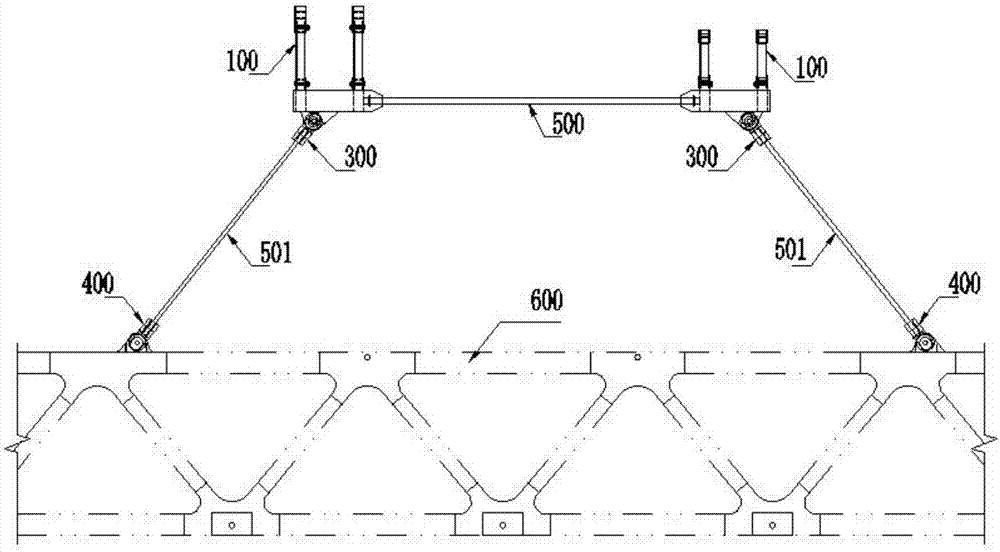
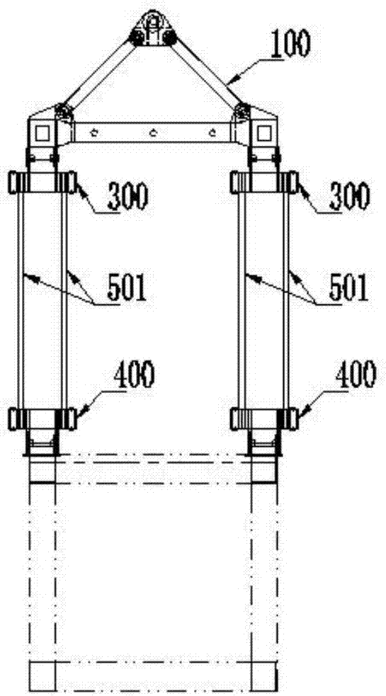
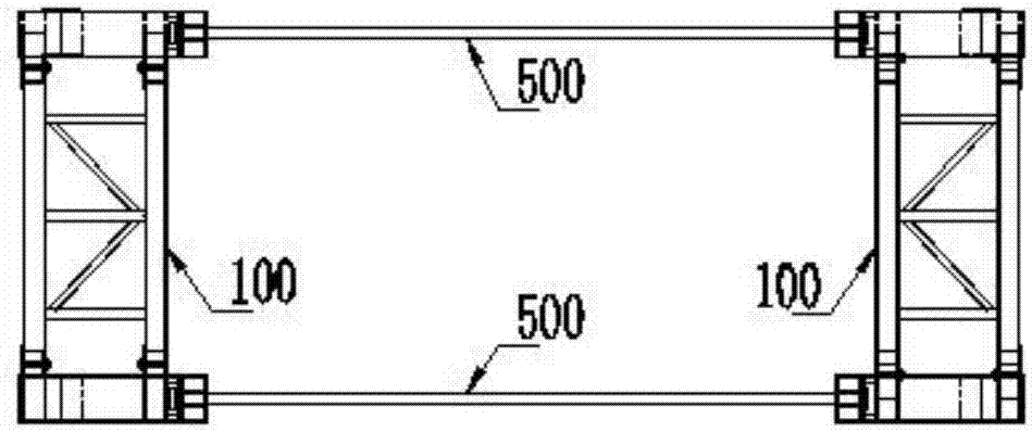
[0038] see Figure 1-Figure 3 As shown, the embodiment of the present invention provides a large-span steel beam hoisting sling, which is used for lifting a large-span steel beam 600, which includes:

[0039] Two booms arranged at intervals, each boom includes a shoulder pole beam 100 and two first stay cables 501, and the top ends of the two first stay cables 501 are respectively connected to two bottom ends of the corresponding shoulder pole beam 100. side; since the steel beam 600 has a rectangular parallelepiped structure, in order to ensure the stability of the steel beam 600 during hoisting, it is necessary to connect one of the first cables 501 on both sides of the steel beam 600, and the two The connecting line between the first cable 501 and the connection point of the steel beam 600 is preferably perpendicular to the length directio...


PUM


Abstract

The invention discloses a long-span steel beam lifting appliance. The long-span steel beam lifting appliance is used for lifting long-span steel beams and comprises two lifting arms, which are arranged at an interval; each lifting arm comprises a carrying pole beam and two first inhaul cables; and the top ends of the two first inhaul cables are respectively connected to two sides of the bottom end of the corresponding carrying pole beam. The long-span steel beam lifting appliance further comprises a second inhaul cable; and the second inhaul cable is horizontally arranged and two ends of the second inhaul cable are fixedly connected with the two carrying pole beams. The invention further discloses a long-span steel beam lifting method. The long-span steel beam lifting appliance has the advantages that the operation space is reduced, the structure is light, the assembling and disassembling are convenient and the long-span steel beam lifting appliance is suitable for the lifting operations of different types of hoisting equipment and the lifting operations of the steel beams with different spans.

Description

technical field [0001] The invention relates to the field of large-scale structure hoisting, in particular to a hoisting tool for a large-span steel girder and a method for hoisting the steel girder. Background technique [0002] In the existing bridge construction, the method of cantilever assembly is usually used for construction. With this method, it is necessary to press weight or anchor at the rear end of the steel beam, and the temporary engineering volume is huge. If this method is used for construction of long-span steel beams, the front end of the cantilever will be deformed greatly, and the construction of the pier at the front end of the cantilever will be difficult and dangerous. [0003] Therefore, in the construction of long-span bridges, it is usually selected to weld the long-span steel girders on land, and then hoist them to a suitable position between the two piers by a spreader for installation. However, the conventional spreader is a fully welded frame s...

Claims


Application Information

Patent Timeline
IPC IPC(8): E01D21/00
CPCE01D21/00
Inventor 卢鹏黄剑锋李方峰欧阳华幸思佳张瑞霞田继开黄晓剑
Owner CHINA RAILWAY MAJOR BRIDGE ENG GRP CO LTD
Why Eureka
Try Eureka