
Paperboard quick coating paper production line

A production line and cardboard technology, applied to layered products, lamination devices, lamination, etc., can solve the problems of low production efficiency of sheet stickers, no automatic feeding and discharging, etc., to achieve good bonding effect, simple structure, and easy output The effect of convenience

Inactive Publication Date: 2017-12-01
长兴鼎盛机械有限公司
View PDF1 Cites 2 Cited by
  • Summary
  • Abstract
  • Description
  • Claims
  • Application Information

AI Technical Summary

Problems solved by technology

[0006] The purpose of the present invention is to address the deficiencies of the prior art, by absorbing and suspending the protective paper and then lifting and lowering to realize the lamination of the sheet material and the protective paper, and linking the feeding and discharging mechanism during the lifting process to realize fast feeding and discharging Then it overcomes the problem that the existing equipment does not have automatic feeding and discharging, and the production efficiency of sheet metal stickers is low.

Method used


Image

  • Paperboard quick coating paper production line
  • Paperboard quick coating paper production line
  • Paperboard quick coating paper production line

Examples


Embodiment 1

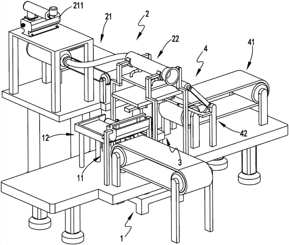
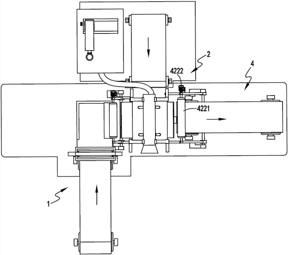
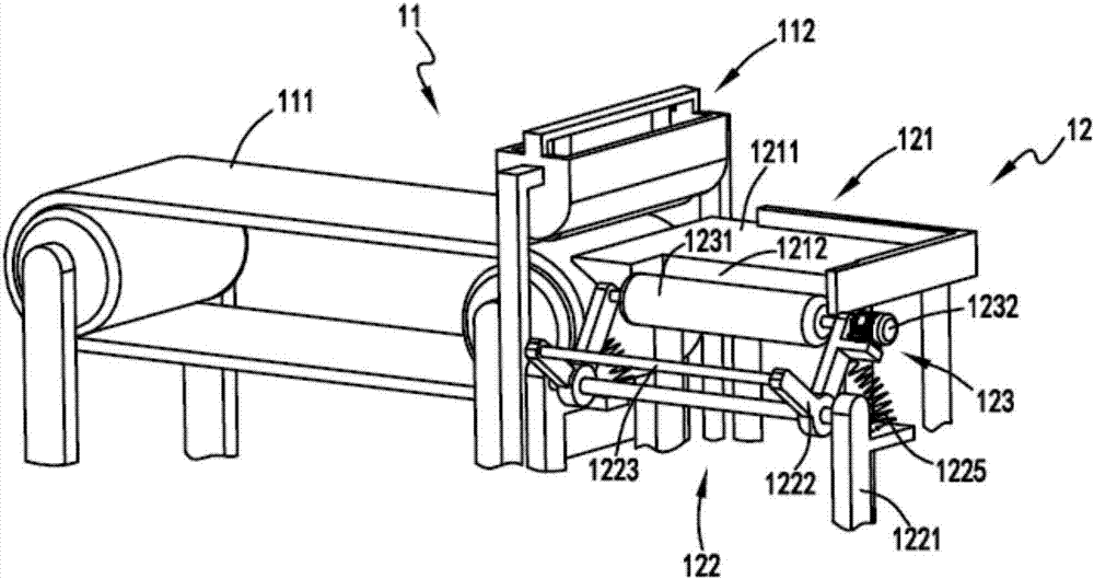
[0040] figure 1 Schematic diagram of the equipment for quickly attaching protective paper to cardboard, figure 2 A schematic top view of the equipment for quickly attaching protective paper to cardboard, image 3 It is a schematic diagram of the structure of the cardboard feeding part, Figure 4 It is a schematic diagram of the structure of the bonding part, Figure 5 It is a schematic diagram of the structure of the feeding part of the protective paper, Figure 6 is a schematic cut-away diagram of the adsorption plate, Figure 7 It is a schematic diagram of the structure when the cardboard and the protective paper start to be laminated, Figure 8 It is a schematic diagram of the structure of the gluing mechanism, Figure 9 It is a schematic diagram of the structure of the negative pressure generating device and the negative pressure adsorption device, Figure 10 It is a schematic diagram of the structure of the rubber box. Such as figure 1 , figure 2 , image 3 , ...

Embodiment 2

[0053] Such as figure 1 , figure 2 , image 3 , Figure 4 , Figure 5 , Figure 6 , Figure 7 , Figure 8 , Figure 9 and Figure 10 As shown, the components that are the same as or corresponding to those in the first embodiment are marked with the corresponding reference numerals in the first embodiment. For the sake of simplicity, only the differences from the first embodiment will be described below. The difference between the second embodiment and the first embodiment is that: the blower device 221 includes a blower 2211; the negative pressure generating device 222 includes a pipeline 2221 and a number of acceleration elements 2222 arranged in the pipeline 2221, and the acceleration elements 2222 is set in the shape of a cone, and one end with a large opening faces the blower 221; the negative pressure adsorption device 223 includes a negative pressure tube 2231 arranged near the small opening end of the accelerator 2222, and is arranged at the end of the negative...


PUM


Abstract

The invention relates to a cardboard rapid paper-coating production line, comprising a cardboard feeding part, the cardboard feeding part includes a gluing mechanism and a feeding mechanism arranged at the rear end of the gluing mechanism; a protective paper feeding part, and a protective paper output part including a transmission mechanism And an adsorption mechanism for absorbing the protective paper transported by the transport mechanism and keeping the protective paper in a suspended state; the bonding part, the bonding part is arranged at the rear end of the feeding mechanism and the lower end of the adsorption mechanism, and the bonding part includes Accept the cardboard conveyed by the feeding mechanism, drive the cardboard to move upwards, and drive the cardboard and the protective paper attached to the cardboard to move down together after bonding with the protective paper on the adsorption mechanism; the output part, the output part includes setting The output mechanism at the rear end of the lifting mechanism and the pressure roller mechanism arranged between the lifting mechanism and the output mechanism; the invention overcomes the problems that the existing equipment does not have automatic material feeding and discharging, and the production efficiency of sheet metal stickers is low.

Description

technical field [0001] The invention relates to the technical field of sticker equipment, in particular to a cardboard rapid paper-coating production line. Background technique [0002] In order to prevent scratches or bruises during subsequent transportation, some sheets are often pasted with a layer of protective paper on their surface after processing. [0003] A Chinese utility model patent with the authorized announcement number CN202037959U, which discloses a film and sticker device on the sheet material uncoiling, leveling, and shearing production line, which accurately sends the sheet material, film tape or paper to the specified position through numerical control equipment Then use the film roller to stick the film, but the equipment has the following problems: [0004] 1. The equipment does not have the function of continuous automatic feeding of the two materials that need to be bonded together. [0005] 2. The equipment does not have the function of automatical...

Claims


Application Information

Patent Timeline
IPC IPC(8): B32B37/00B32B37/12
CPCB32B37/0053B32B37/12
Inventor 丁伟平
Owner 长兴鼎盛机械有限公司
Learn More